Schneider BMEAHO0412 Retrofit-Ready Analog Output for M580: Compatible Modernization and Smooth Legacy System Upgrade
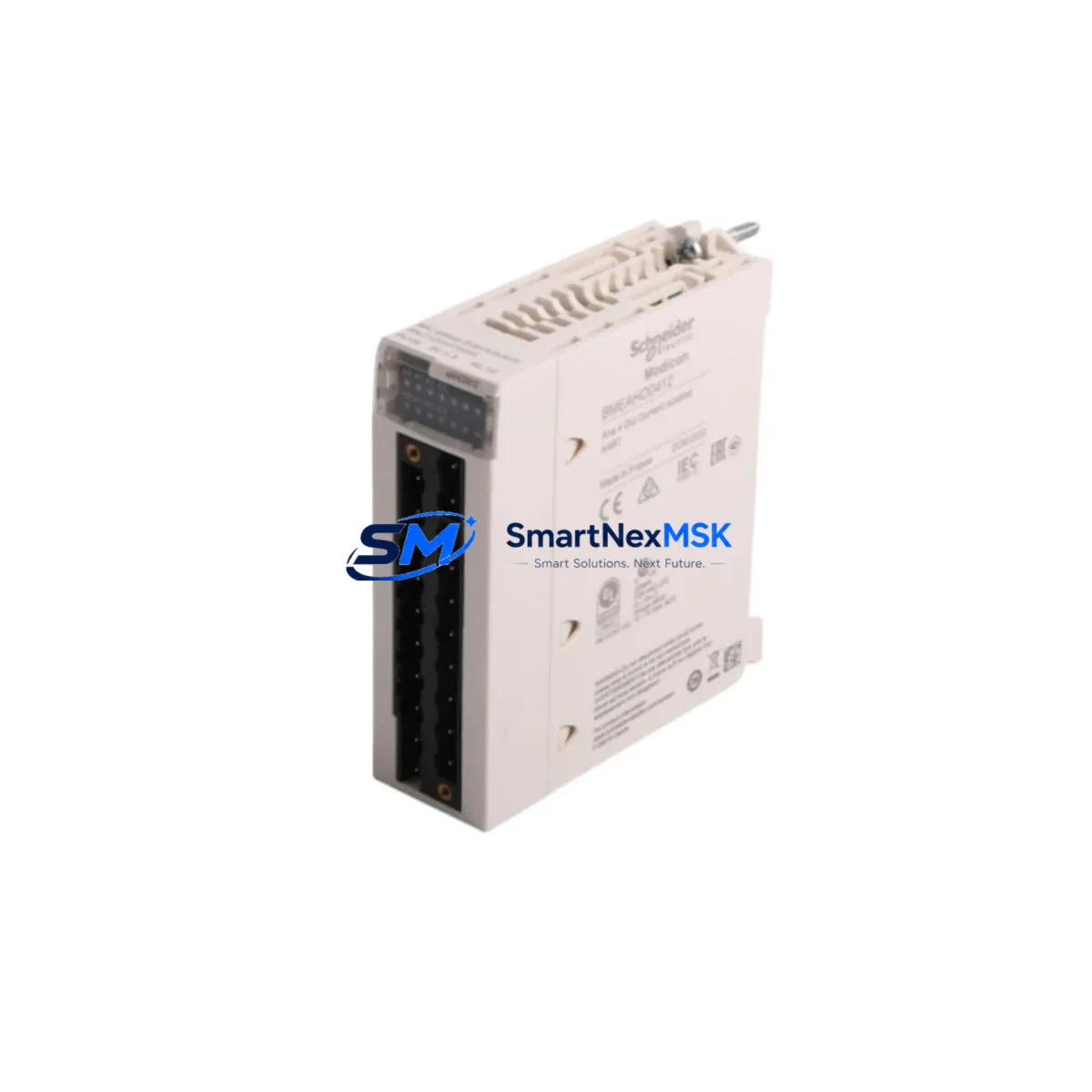
The Schneider Electric BMEAHO0412 is a 4-channel analog output module engineered for the Modicon M580 ePLC platform. As aging Modicon Quantum and Modicon Premium control systems reach end-of-life, the BMEAHO0412 has become a critical component in retrofit projects that demand signal continuity, rack compatibility, and minimal disruption to existing process logic. Whether you are migrating from a legacy Quantum 140 series rack or upgrading a Premium TSX platform, this module provides the analog output resolution and channel density required to maintain precise field device control throughout the transition.
At SMARTNEXMSK, we supply the BMEAHO0412 from verified stock with full functional testing, 12-month warranty coverage, and same-week dispatch to support time-sensitive plant shutdowns and emergency replacement scenarios.
Upgrade Compatibility Table
| Parameter | BMEAHO0412 (M580) | Legacy Reference (Quantum/Premium) |
|---|---|---|
| Output Channels | 4 channels (0–20 mA / 4–20 mA / 0–10 V) | 140 AVO 02000 / TSX AEY 414 |
| Rack / Backplane | M580 X80 backplane (BMEXBP0400 / BMEXBP0800) | Quantum 140 XBP series — not directly compatible |
| Communication Interface | Ethernet-based X80 bus (EtherNet/IP + Modbus TCP) | S908 remote I/O bus (Quantum) / Fipio (Premium) |
| Programming Environment | EcoStruxure Control Expert (Unity Pro ≥ 13.1) | Concept / PL7 Pro |
| Installation Requirement | DIN-rail or panel mount via M580 rack | Dedicated Quantum / Premium rack required |
| Replacement Recommendation | Direct slot replacement within M580 X80 rack | Rack adapter or full rack migration required |
| Commissioning Focus | Module address, I/O mapping, scaling verification | Re-map channel addresses in Control Expert |
| Warranty | 12 Months — SMARTNEXMSK Tested & Certified | |
Retrofit Planning for Existing Automation Systems
Successful integration of the BMEAHO0412 into a brownfield automation environment requires systematic pre-migration planning. The first step is a rack audit: confirm that the target BMEXBP0400 or BMEXBP0800 backplane has an available slot with sufficient power budget. The M580 CPU — typically a BMEP582040 or BMEP584020 — allocates bus power across all installed modules, and adding a 4-channel analog output module increases the total draw. Review the rack power consumption report in Control Expert before committing to the slot assignment.
Terminal wiring is the next critical checkpoint. The BMEAHO0412 uses a 20-pin removable terminal block. If you are replacing a Quantum 140 AVO 02000, the field wiring must be re-terminated to match the M580 pinout. Label each wire before disconnection and photograph the existing terminal layout. For 4–20 mA current loop outputs driving control valves or variable frequency drives, verify that the load impedance of each field device falls within the module’s specified output compliance range to avoid signal clipping during commissioning.
On the software side, open the existing Control Expert project and locate the analog output DDT (Derived Data Type) associated with the legacy module. The BMEAHO0412 uses the standard T_M_ANA_OUT_B DDT structure. If migrating from a Concept-based Quantum project, the I/O variable mapping must be re-created in Control Expert’s I/O configuration editor. Pay particular attention to channel scaling: the BMEAHO0412 supports configurable output ranges per channel, and any mismatch between the software scaling parameters and the field device’s input range will result in incorrect process output values.
Communication link verification is essential when the BMEAHO0412 is installed in a remote X80 drop connected via a BMECRA31210 or BMXCRA31200 communication adapter. Confirm that the EtherNet/IP scanner configuration in the M580 CPU correctly references the new module’s slot position and that the RPI (Requested Packet Interval) is set appropriately for the process response time requirements. For systems using a BMENOC0301 or BMENOC0311 network option card for Modbus TCP connectivity to SCADA, verify that the analog output register map remains consistent after the module swap to avoid HMI display errors.
HMI screen validation is often overlooked during analog output module replacements. If the plant uses a Magelis HMIGTO or HMISCU panel connected via Modbus TCP, confirm that the output register addresses referenced in the HMI project match the new module’s I/O mapping. A simple register offset error can cause operators to send incorrect setpoints to field devices, creating process upsets during the first post-migration production run.
For systems where the BMEAHO0412 is part of a larger I/O expansion strategy, consider the co-installation of a BMXAMI0810 analog input module or a BMXDDO1602 digital output module in adjacent rack slots to consolidate field wiring and reduce cabinet footprint. If the retrofit also involves upgrading the power supply, the BMXCPS2000 or BMXCPS3500A rack power supply modules provide the regulated 24 VDC bus voltage required by the X80 I/O family.
Downtime Control During System Migration
Minimizing production downtime during an analog output module replacement requires a structured cutover plan. Begin by creating a full backup of the Control Expert project — including the symbol table, I/O configuration, and communication settings — before any hardware is removed from the rack. Store the backup on an isolated engineering workstation and verify the archive integrity before proceeding.
Where process conditions allow, perform a staged migration: keep the legacy module energized and the field device in manual control mode while the new BMEAHO0412 is pre-configured in a bench test environment. Use a spare M580 rack or a portable test bench with a BMEP581020 CPU to validate the module’s channel outputs against calibrated reference instruments before installation in the live panel. This approach allows the commissioning engineer to confirm scaling, wiring, and DDT mapping without occupying the production rack.
During the live cutover window, follow a defined sequence: de-energize the rack slot, remove the legacy module, insert the BMEAHO0412, restore power, and perform an online download of the updated Control Expert project. Use the Control Expert diagnostic viewer to confirm that all four output channels report healthy status and that the output values match the expected process setpoints. If the system uses a TSXPCX3030 or USB programming cable for local access, ensure the cable is connected and the CPU is in RUN mode before releasing the field devices from manual control.
Document the as-built wiring changes, updated I/O mapping, and any modified HMI register addresses in the plant’s maintenance management system. This documentation is essential for future troubleshooting and supports the 12-month warranty claim process if a module fault is detected after installation.
Retrofit Support FAQ
Q1: Is the BMEAHO0412 a direct drop-in replacement for the Quantum 140 AVO 02000 analog output module?
No — the BMEAHO0412 is designed for the Modicon M580 X80 backplane and is not physically or electrically compatible with the Quantum 140-series rack. A full rack migration to the M580 platform is required. However, the field wiring and process signals can be reused after re-termination to the BMEAHO0412’s terminal block pinout. SMARTNEXMSK can supply both the BMEAHO0412 and compatible M580 rack components to support a complete migration kit.
Q2: What pre-shipment testing does SMARTNEXMSK perform on the BMEAHO0412?
Every BMEAHO0412 unit is powered up and functionally tested on an M580 X80 rack prior to dispatch. Channel output accuracy is verified across the full 0–20 mA and 0–10 V ranges using calibrated test equipment. Units that pass all functional checks are shipped with a test report and are covered by a 12-month warranty from the date of delivery.
Q3: Can the BMEAHO0412 operate in a remote X80 drop connected via EtherNet/IP?
Yes. The BMEAHO0412 is fully compatible with remote X80 drops managed by a BMECRA31210 or BMXCRA31200 communication adapter. Ensure that the EtherNet/IP scanner in the M580 CPU is configured with the correct IP address and slot mapping for the remote drop, and that the network switch connecting the drop supports the required RPI cycle time without packet loss.
Q4: What should I verify during commissioning after installing the BMEAHO0412?
After installation, verify the following in sequence: (1) module status LED shows green in Control Expert diagnostics; (2) all four output channels are mapped correctly in the I/O configuration; (3) output scaling matches field device input ranges; (4) HMI register addresses are consistent with the updated I/O mapping; (5) field devices respond correctly to setpoint changes from the SCADA or HMI system. Document all commissioning results and retain them for warranty reference.
© 2026 SMARTNEXMSK. All rights reserved.
Original Source: https://smartnexmsk.com
Contact: sales@smartnexmsk.com | +86 18259474341