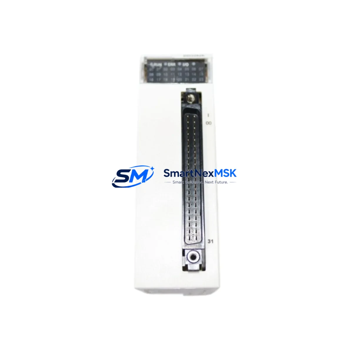
Schneider Electric 140CPU43412 Maintenance-Ready Spare for Quantum Automation
The Schneider Electric 140CPU43412 is a high-performance CPU module designed for the Modicon Quantum PLC platform — one of the most widely deployed process automation architectures in heavy industry, utilities, oil & gas, and manufacturing. When this module fails or reaches end-of-service life, the consequences are immediate: unplanned downtime, halted production lines, and costly emergency procurement. Stocking a verified original 140CPU43412 spare is the single most effective measure a maintenance team can take to protect system uptime and reduce mean time to recovery (MTTR).
At SMARTNEXMSK, every 140CPU43412 unit is sourced from authorized supply chains, individually tested under operational conditions, and shipped with a 12-month warranty. Whether you are executing a planned replacement during a scheduled outage or responding to an unplanned fault, our inventory is ready for same-week dispatch.
Spare Maintenance Table
| Parameter | Specification |
|---|---|
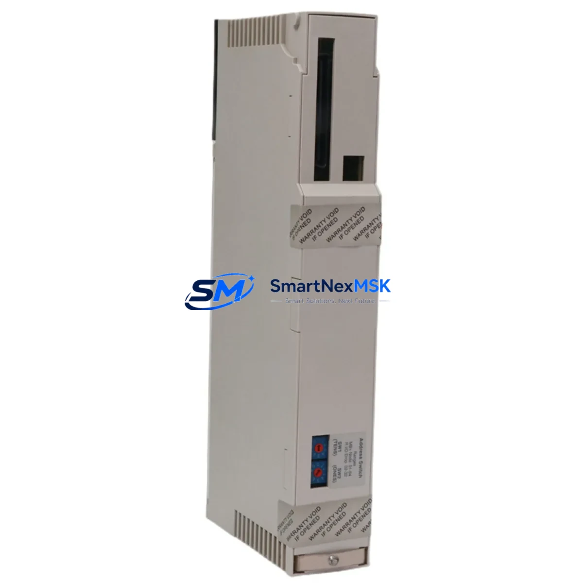
| Part Number / SKU | 140CPU43412 |
| Brand | Schneider Electric (Modicon) |
| Series | Modicon Quantum |
| Module Type | PLC CPU Module |
| Processor | Motorola 68040, 32-bit |
| Memory | 512 KB RAM (user logic), 1 MB Flash |
| Communication Ports | Modbus Plus, RS-232 (Modbus RTU) |
| I/O Capacity | Up to 64,000 discrete / 4,000 analog I/O points |
| Backplane Compatibility | Modicon Quantum 140 series backplanes (6, 10, 16 slot) |
| Power Supply Compatibility | 140CPS11100, 140CPS21100, 140CPS41400 |
| Operating Temperature | 0°C to 60°C |
| Humidity | 5% to 95% non-condensing |
| Origin | France |
| Certification | CE, UL, cUL |
| Installation | DIN rail / panel mount via Quantum backplane slot |
| Warranty | 12 Months (SMARTNEXMSK) |
| Pre-shipment Test | Functional power-on and communication verification |
Maintenance Planning for Continuous Operation
Replacing a 140CPU43412 in a live Quantum system is rarely an isolated task. Experienced maintenance engineers know that a CPU fault is often symptomatic of broader stress across the control cabinet. Before or during a CPU swap, the following components should be inspected and, where appropriate, replaced as part of the same maintenance window:
The 140CPS11100 or 140CPS21100 power supply module is the first item to verify — an aging or under-spec power supply is a leading cause of CPU instability and unexpected resets. Alongside the power supply, inspect the 140XBP01600 or 140XBP01000 backplane for corrosion, bent connector pins, or heat damage, as a degraded backplane can cause intermittent CPU communication faults that are difficult to diagnose without physical inspection.
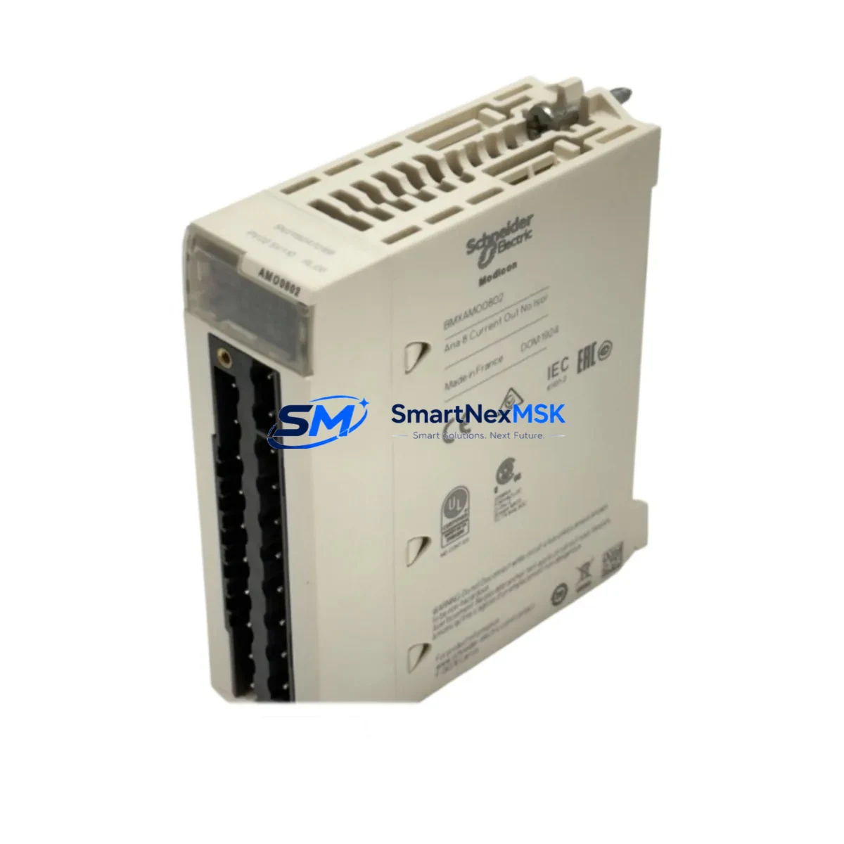
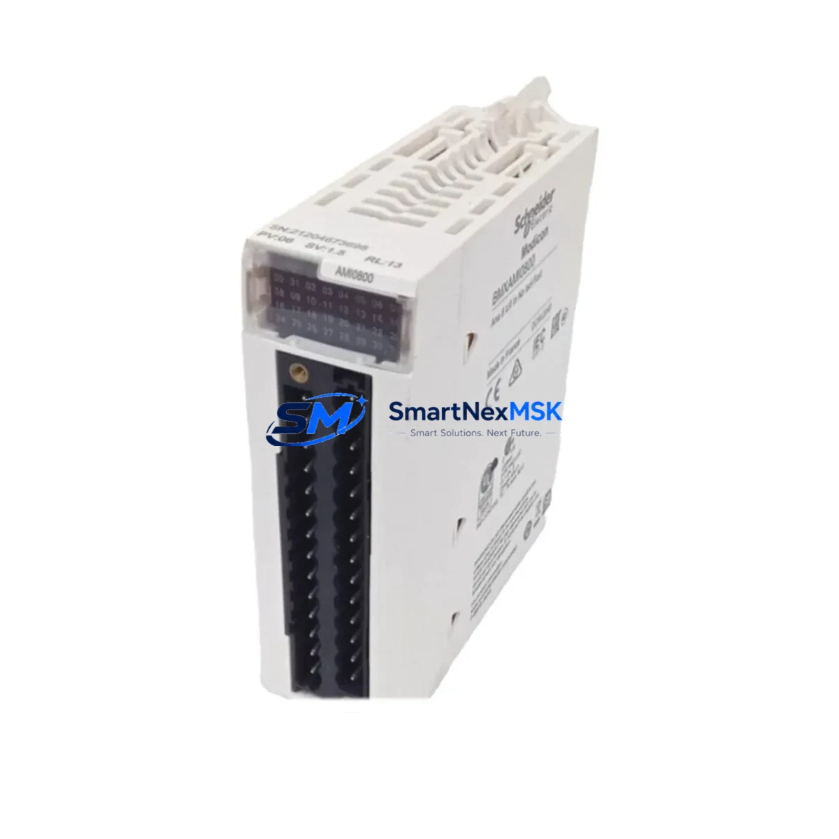
I/O integrity is equally critical. Discrete input modules such as the 140DAI54000 and output modules like the 140DAO84000 should be checked for blown fuses, relay wear, and terminal block tightness. Analog I/O modules — particularly the 140AII33000 — should be verified for signal drift, which can indicate power rail noise or grounding issues that will affect the new CPU’s performance as well.
Communication continuity must be confirmed before returning the system to service. The 140NOE77100 Ethernet communication module and any 140NOM21100 Modbus Plus network option module should be tested for link integrity. If the system uses a 140NRP95400 RIO head-end module for remote I/O drops, verify that the coaxial cable connections and terminators are intact — a single bad terminator can prevent the new CPU from establishing communication with remote racks.
For systems with HMI integration, confirm that the Magelis or XBTGT series HMI panel is communicating correctly via Modbus or Ethernet after the CPU replacement. Signal isolators on 4–20 mA loops and 140ACO02000 analog output modules should also be checked, as CPU replacement sometimes exposes pre-existing signal integrity issues that were masked by the previous module’s fault state.
Finally, review the battery backup module (140CPU43412 includes an onboard lithium battery for RAM retention) and replace it if the battery life indicator shows degradation. A fresh battery ensures that the user program and data tables are retained through any subsequent power interruption.
Site Replacement Workflow
Step 1 — Pre-replacement documentation: Export the current PLC program from Unity Pro or Concept software and save a timestamped backup. Record all I/O addresses, network node numbers, and Modbus Plus addresses configured in the existing CPU.
Step 2 — Safe shutdown: Place the system in a controlled stop state. Notify process operators and confirm that all field devices are in a safe condition before de-energizing the control cabinet.
Step 3 — Module extraction: With the backplane de-energized, release the CPU module locking tab and slide the 140CPU43412 out of slot 1 (or the designated CPU slot). Handle the module by its edges to avoid ESD damage.
Step 4 — Spare installation: Insert the replacement 140CPU43412 into the same backplane slot. Ensure the module is fully seated and the locking tab is engaged. Reconnect any RS-232 or Modbus Plus cables.
Step 5 — Program restore and verification: Re-energize the backplane and power supply. Download the saved program via Unity Pro or Concept. Verify that all I/O modules are recognized, communication modules establish their links, and the CPU enters RUN mode without fault codes.
Step 6 — Functional test: Perform a loop check on critical I/O points. Confirm HMI displays are updating correctly and that remote I/O drops are communicating. Log the replacement in the site maintenance record.
This workflow minimizes downtime to a single planned outage window and eliminates the risk of configuration errors that can extend recovery time when working under pressure.
Spare Parts Support FAQ
Q1: Is the 140CPU43412 a direct drop-in replacement for older Quantum CPU models such as the 140CPU43412A or 140CPU43412U?
A: The 140CPU43412 is functionally compatible with the Modicon Quantum backplane and can replace earlier CPU variants in the same series. However, firmware version differences may require a program re-download via Unity Pro or Concept. Always verify the software version compatibility before installation and perform a full functional test after replacement.
Q2: How does SMARTNEXMSK verify the condition of spare 140CPU43412 units before shipment?
A: Each unit undergoes a power-on functional test, communication port verification, and visual inspection for physical damage, corrosion, or component wear. Units that do not pass all checks are not offered for sale. A test report is available upon request for critical applications.
Q3: What is the recommended spare inventory strategy for a facility running multiple Quantum PLC racks?
A: Industry best practice for critical automation infrastructure is to maintain at least one CPU spare per production line or process unit, with a minimum of two spares for facilities with more than five Quantum racks. Given the 140CPU43412’s role as the system’s central processing unit, a single failure without a spare on hand can result in days of downtime while sourcing a replacement through standard channels. SMARTNEXMSK supports long-term supply agreements for facilities requiring guaranteed stock availability.
Q4: What does the 12-month warranty cover, and what is the claims process?
A: The 12-month warranty covers manufacturing defects and functional failures under normal operating conditions. It does not cover damage resulting from incorrect installation, overvoltage, or physical mishandling. To initiate a warranty claim, contact sales@smartnexmsk.com with the order number, a description of the fault, and any available diagnostic information. Replacement units are dispatched upon fault confirmation, minimizing the impact on your operations.
© 2026 SMARTNEXMSK. All rights reserved.
Original Source: https://smartnexmsk.com
Contact: sales@smartnexmsk.com | +86 18259474341