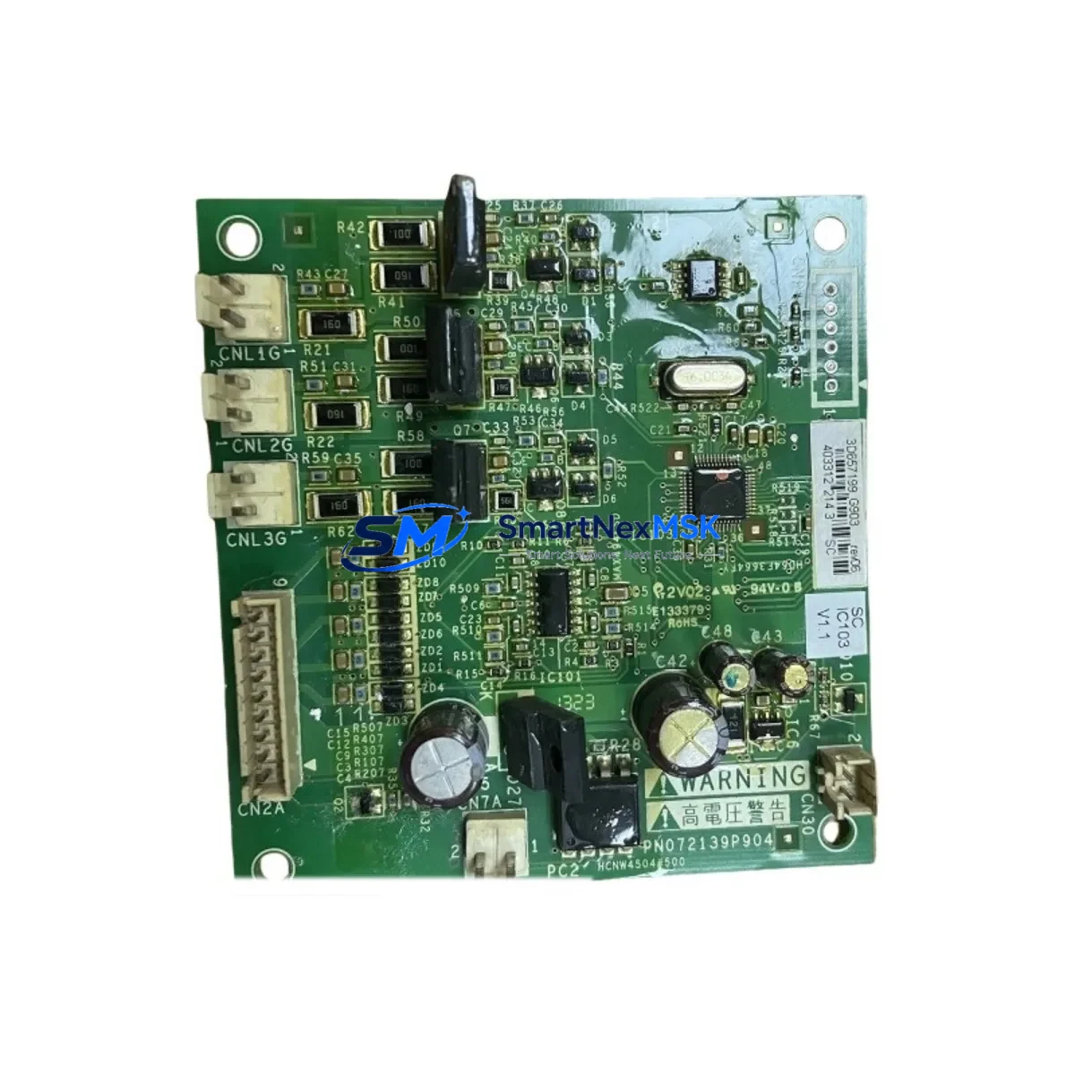
Schneider Electric PN072139P904 Retrofit-Ready Drive Board for ATV Series Control Systems
The Schneider Electric PN072139P904 is a retrofit-ready inverter drive board engineered for seamless integration into Altivar (ATV) series variable frequency drives. As legacy ATV units reach end-of-life or become increasingly difficult to source through OEM channels, the PN072139P904 provides a verified drop-in replacement path that preserves existing wiring configurations, control logic, and communication links — minimizing engineering rework and unplanned downtime on the production floor.
This board is commonly deployed in modernization projects involving ATV312, ATV320, and ATV340 drive platforms, where the original power stage or drive board has failed or is no longer available as a factory spare. Engineers and maintenance teams sourcing this component can expect full compatibility with the standard ATV terminal block layout, including the R/S/T power input terminals, U/V/W motor output terminals, and the 24 VDC control supply rail. No mechanical modification to the drive enclosure or control cabinet is required in the majority of retrofit scenarios.
Upgrade Compatibility Table
| Parameter | Details |
|---|---|
| Part Number | PN072139P904 |
| Brand | Schneider Electric |
| Compatible Series | Altivar ATV312 / ATV320 / ATV340 |
| Function | Inverter Drive / Power Board |
| Interface | Standard ATV terminal block (R/S/T, U/V/W, 24 VDC control rail) |
| Installation | Direct board swap; no enclosure modification required |
| Communication Compatibility | Modbus RTU, CANopen (platform-dependent) |
| Replacement Recommendation | Verified drop-in for failed or EOL ATV drive boards |
| Commissioning Notes | Verify motor parameter set, acceleration/deceleration ramps, and fault history reset after swap |
| Warranty | 12 Months |
| Origin | China (CN) |
| Shipping | Fast global dispatch from Xiamen |
Retrofit Planning for Existing Automation Systems
A successful retrofit using the PN072139P904 begins well before the board arrives on-site. Maintenance engineers should first audit the existing ATV drive’s nameplate data — rated voltage, output current, and motor power — to confirm the replacement board’s power stage rating matches the installed drive frame size. In multi-drive control cabinets where several ATV320 or ATV340 units share a common DC bus, it is equally important to verify that the LXM32 servo drive or adjacent frequency converters on the same bus are not contributing to voltage spikes that could stress the new board during initial power-up.
Terminal wiring should be documented with photographs before disassembly. The ATV series uses a consistent terminal numbering scheme, but field modifications — such as added braking resistor connections via a VW3A7005 braking unit or external EMC filter wiring — must be re-verified against the original wiring diagram. If the drive communicates over Modbus RTU via an RJ45 serial link or through a VW3A3607 Ethernet/IP communication card, the communication card itself should be inspected for damage before reuse; a faulty card can mask a successful board swap and generate misleading fault codes on the Magelis HMIGTO HMI panel.
For systems using Modicon M340 or Modicon M580 PLCs as the upstream controller, confirm that the drive’s Modbus node address and baud rate settings stored in the ATV’s EEPROM are preserved. Many ATV drives retain parameter sets through a power cycle, but a board swap that involves replacing the control board’s non-volatile memory section may reset these values to factory defaults. Re-entering the motor control parameters — including rated frequency, motor cos φ, and IR compensation — is a mandatory commissioning step. Where a SoMove parameter file was previously saved, it can be re-uploaded via the VW3A8104 USB programming cable to restore the full parameter set in minutes rather than hours.
I/O expansion modules connected to the ATV’s logic I/O terminals — such as analog input cards for 4–20 mA speed reference signals or digital output relays for fault annunciation — should be tested individually after the board swap to confirm signal integrity. In older installations where the ATV71 or ATV61 is being migrated to a newer ATV3xx platform using the PN072139P904 as an intermediate repair step, engineers should also review whether the existing Profibus DP or DeviceNet communication option card is compatible with the replacement board’s backplane connector pinout.
Downtime Control During System Migration
Minimizing production downtime during a drive board replacement requires a structured pre-swap checklist and a tested rollback plan. Before isolating the drive, capture a full parameter backup using SoMove or the ATV’s built-in parameter copy function if a VW3A58101 remote keypad with memory card is installed. This ensures that if the replacement board requires re-commissioning, the original parameter set is available for immediate restoration without relying on paper records.
Schedule the physical swap during a planned maintenance window or shift changeover. Isolate the drive from the main power supply and verify zero-voltage lockout on the DC bus capacitors — typically a minimum 5-minute discharge period for ATV drives in the 15–75 kW range — before touching any internal components. Label all control wiring with numbered ferrules before disconnection. The PN072139P904 board swap itself typically takes 20–40 minutes for a trained technician familiar with the ATV frame architecture.
After installation, perform a no-load motor run test at reduced speed (10–15 Hz) before restoring full process speed reference. Monitor the drive’s thermal sensor readings and output current waveform during the first 30 minutes of operation. Confirm that all upstream Modicon PLC I/O status bits reflect the correct drive state — running, at-speed, and fault-free — before releasing the line back to production. All units supplied by SMARTNEXMSK undergo pre-shipment functional testing and are covered by a 12-month warranty from the date of delivery.
Retrofit Support FAQ
Q1: Is the PN072139P904 a direct replacement for the original Schneider Electric board in my ATV drive?
Yes. The PN072139P904 is a verified replacement board for compatible ATV series drives. Before installation, confirm your drive’s frame size and power rating match the board’s specifications. If you are unsure, share your drive’s nameplate data with our technical team at sales@smartnexmsk.com for pre-sale compatibility confirmation.
Q2: Will my existing motor parameters and communication settings be preserved after the board swap?
In most cases, parameter data is stored in the drive’s control board EEPROM. If the PN072139P904 replaces only the power/drive board without affecting the control board, parameters are typically retained. However, we recommend performing a full parameter backup via SoMove or the VW3A8104 USB cable before any board replacement as a precaution.
Q3: What pre-shipment testing does the PN072139P904 undergo?
Every PN072139P904 unit dispatched by SMARTNEXMSK is subject to functional power-on testing and visual inspection before shipment. Units are packed in anti-static ESD packaging with foam cushioning to prevent transit damage. A 12-month warranty covers manufacturing defects and functional failures under normal operating conditions.
Q4: Can this board be used in a system currently running Profibus DP or Modbus RTU communication?
Yes, provided the communication option card (e.g., VW3A3607 for Ethernet/IP or the Profibus DP card) is separately intact and compatible with the ATV platform. The PN072139P904 drive board itself does not alter the communication card slot interface. Verify the option card’s firmware version is compatible with your PLC’s communication driver after the swap.
© 2026 SMARTNEXMSK. All rights reserved.
Original Source: https://smartnexmsk.com
Contact: sales@smartnexmsk.com | +86 18259474341