Schneider LUFP7 ABC-PDP-SE Retrofit-Ready Profibus DP Module for Altivar Control Systems
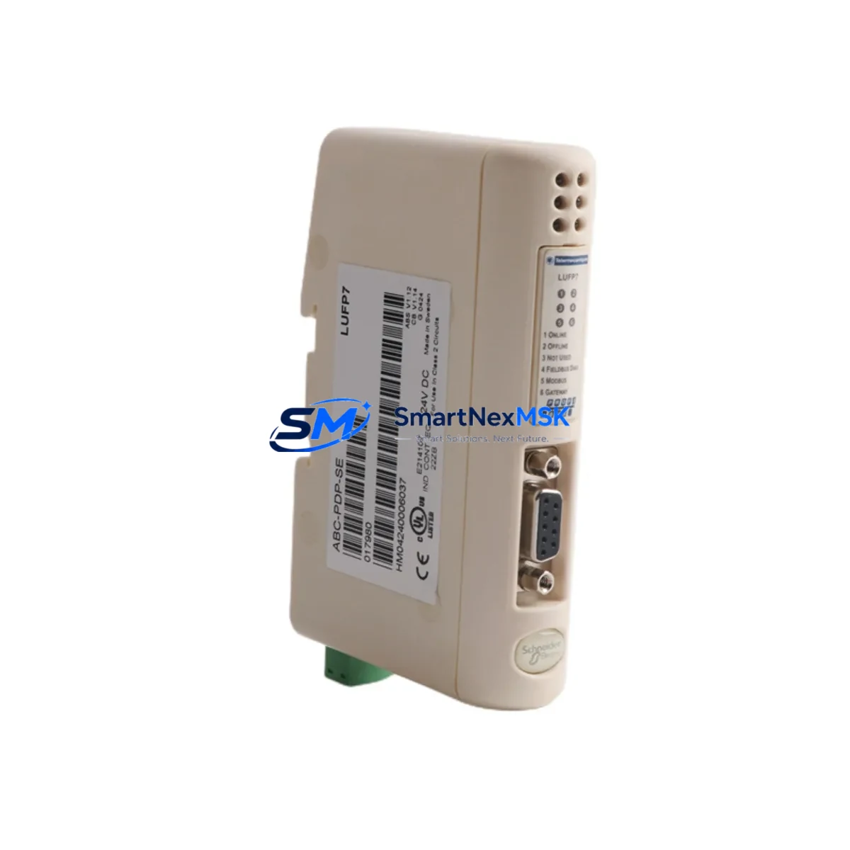
The Schneider Electric LUFP7 ABC-PDP-SE is a Profibus DP slave fieldbus communication module engineered for seamless integration into Altivar variable speed drive platforms, including the ATV31, ATV58, ATV71, and ATV312 series. As legacy automation infrastructure ages and OEM support windows close, the LUFP7 ABC-PDP-SE has become a critical retrofit component for engineers tasked with modernizing distributed control architectures without replacing entire drive cabinets or rewriting PLC programs from scratch.
This module slots directly into the option card bay of compatible Altivar drives, establishing a Profibus DP slave node that communicates with upstream Siemens S7-300, S7-400, or S7-1500 PLCs, as well as Schneider Modicon M340 and Premium controllers operating as Profibus DP masters. The physical installation requires no additional mounting hardware beyond the drive’s existing option slot, and the module draws power directly from the drive’s internal bus — eliminating the need for an external 24 VDC supply in most retrofit scenarios.
Upgrade Compatibility Table
| Parameter | LUFP7 ABC-PDP-SE Specification | Retrofit Notes |
|---|---|---|
| Compatible Drives | ATV31, ATV58, ATV71, ATV312 | Verify option slot type (LU•/VW3A•) before ordering |
| Communication Protocol | Profibus DP (EN 50170 / IEC 61158) | Slave node; DP master must be configured in GSD file |
| Baud Rate | 9.6 kbps – 12 Mbps (auto-detect) | Match master baud rate; no manual switch required |
| Node Address | 1–125 (DIP switch configurable) | Set address before power-on; conflicts cause bus fault |
| Connector Interface | DB9 female (Profibus standard) | Use shielded Profibus cable; terminate end nodes |
| Power Supply | Powered via drive option slot (internal bus) | No external 24 VDC required in standard installations |
| GSD File | Schneider-supplied .GSD for STEP 7 / Unity Pro | Import GSD before hardware configuration in PLC IDE |
| Replaces / Supersedes | VW3A3607, earlier LUFP• variants | Confirm firmware version compatibility with drive |
| Commissioning Tool | SoMove, PowerSuite, or drive keypad | Set COM card parameters via menu r-I-O or CTL |
| Warranty | 12 Months | Covers manufacturing defects; includes pre-shipment test |
Retrofit Planning for Existing Automation Systems
A successful retrofit using the LUFP7 ABC-PDP-SE begins well before the module arrives on site. Engineers should audit the existing control cabinet to confirm the Altivar drive’s option slot is unoccupied or that the current card — often an older VW3A3607 Profibus adapter or a legacy LUFP2 DeviceNet module — can be safely removed without disrupting adjacent I/O assignments. In multi-drive panels, it is common to find the Altivar ATV71 sharing a control cabinet with a Schneider TeSys D contactor bank and a Modicon STB island bus for distributed I/O; the LUFP7 retrofit must be planned around the existing terminal wiring to avoid re-labeling the entire cabinet.
Before powering down, document the drive’s full parameter set using SoMove or the VW3A1101 USB-RJ45 programming cable. Save the parameter file to a local backup — this is especially important when the ATV71 or ATV312 is running a customized speed reference profile or a multi-pump sequencing macro. Once the LUFP7 ABC-PDP-SE is seated in the option slot, restore parameters and verify that the COM card assignment (parameter bUS or r-I-O depending on firmware) is set to Profibus DP rather than the default CANopen or Modbus RTU.
On the PLC side, import the Schneider-supplied GSD file into your Siemens STEP 7 or TIA Portal project, or into the Unity Pro hardware catalog if the master is a Modicon M340 with a BMXNOE0100 Ethernet/Profibus bridge. Assign the correct I/O byte count — typically 4 bytes IN / 4 bytes OUT for basic speed and status control — and map the process data words to the existing function block inputs. If the original program used a Modbus RTU link via an ATV58 with a VW3A58202 serial card, the migration to Profibus DP will require remapping speed reference and fault word bit assignments, as the process data object (PDO) structure differs between protocols.
For cabinets that also house a Schneider XBTGT HMI panel communicating with the drive over a serial link, verify that the HMI’s drive communication driver is updated to reflect the new Profibus node address and that any animated objects tied to drive speed or fault status are re-tested in simulation mode before live commissioning. Similarly, if a Schneider PM5350 power meter or iEM3155 energy meter shares the same RS-485 bus as the original drive serial port, confirm that removing the serial card does not break the metering chain.
Downtime Control During System Migration
Minimizing unplanned downtime is the primary concern in any live production retrofit. For the LUFP7 ABC-PDP-SE installation, the recommended approach is a staged hot-swap procedure: pre-configure the module’s DIP switch node address on the bench, import and compile the GSD-based hardware configuration in the PLC offline, and prepare a parameter backup of the target drive before the maintenance window opens.
During the window, the sequence is: power down the drive, remove the existing option card, seat the LUFP7 ABC-PDP-SE, restore drive parameters from backup, power up, and verify Profibus bus status LED (BF LED off = bus active). Total physical swap time is typically under 15 minutes for a trained technician. The PLC program does not need to be modified if the process data mapping was pre-aligned during offline preparation — the existing speed reference and control word function blocks continue to operate without change, preserving the original ladder or structured text logic intact.
For critical processes where even a 15-minute window is unacceptable, a parallel commissioning strategy is possible: install a second ATV71 with the LUFP7 ABC-PDP-SE pre-configured on a test bench, validate full Profibus communication and drive response, then perform a direct panel swap during a scheduled production break. This approach is particularly effective in food processing, water treatment, and continuous manufacturing lines where control continuity is contractually required.
Retrofit Support FAQ
Q1: Can the LUFP7 ABC-PDP-SE directly replace a VW3A3607 Profibus card in an ATV71 without changing the PLC program?
In most cases, yes. Both modules implement the Profibus DP slave protocol and use compatible process data structures. However, you should verify the GSD file version and confirm that the I/O byte count configured in the PLC hardware table matches the LUFP7’s default PDO size. Minor adjustments to the hardware configuration in STEP 7 or TIA Portal may be required, but the PLC application program (OB1, FBs, DBs) typically requires no modification.
Q2: What wiring changes are needed when migrating from a Modbus RTU serial card to the LUFP7 ABC-PDP-SE?
The Modbus RTU serial card uses an RJ45 or terminal block connector for RS-485 wiring, while the LUFP7 ABC-PDP-SE uses a DB9 female Profibus connector. You will need to run a shielded Profibus cable (Type A, 150 Ω) from the nearest Profibus segment tap or repeater to the drive cabinet. Ensure the cable shield is grounded at one end only, and install a Profibus bus terminator (active termination plug) if the drive is at the physical end of the bus segment.
Q3: How do I verify the LUFP7 ABC-PDP-SE is communicating correctly after installation?
After power-up, check the module’s BF (Bus Fault) LED — it should be off when the Profibus master has established a valid data exchange cycle. On the PLC side, monitor the diagnostic buffer in STEP 7 or TIA Portal for station fault messages. In the drive’s display menu, navigate to the communication monitoring parameter (typically nEt or COM) to confirm the fieldbus reference is active. A pre-shipment communication test is performed on all units before dispatch, and the test report is available on request.
Q4: What does the 12-month warranty cover, and what is the return process?
The 12-month warranty covers all manufacturing defects, component failures, and communication faults attributable to the module itself under normal operating conditions (per IEC 61131-2 environmental ratings). It does not cover damage from incorrect installation, overvoltage, or physical impact. To initiate a warranty claim, contact our technical team with the order reference and a description of the fault symptom. Replacement units are dispatched within 3 business days of fault confirmation, and a pre-paid return label is provided for the defective module.
© 2026 SMARTNEXMSK. All rights reserved.
Original Source: https://smartnexmsk.com
Contact: sales@smartnexmsk.com | +86 18259474341