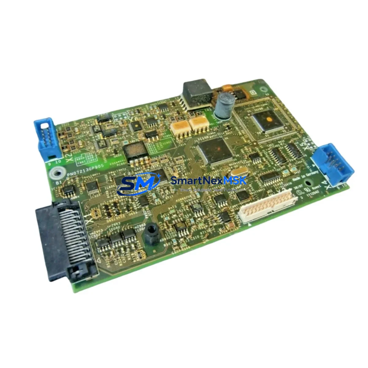
Schneider PN072130P905 Retrofit-Ready VFD Control Board for Altivar Control Systems
The Schneider Electric PN072130P905 is a retrofit-ready VFD (Variable Frequency Drive) control board engineered for seamless integration into legacy Altivar series drive systems. As industrial facilities face increasing pressure to modernize aging automation infrastructure without full system overhauls, the PN072130P905 provides a cost-effective, drop-in upgrade path that preserves existing wiring, cabinet layouts, and motor control logic. Whether you are replacing a failed board in an ATV58, ATV61, or ATV71 series drive, or upgrading a control platform to meet current communication and safety standards, this board delivers the compatibility and reliability your operation demands.
Sourced from verified supply channels and subject to full functional testing prior to shipment, each PN072130P905 unit is backed by a 12-month warranty. Our inventory is maintained to support urgent replacement scenarios, minimizing unplanned downtime in continuous-process and discrete manufacturing environments alike.
Upgrade Compatibility Table
| Parameter | Details |
|---|---|
| Compatible Drive Series | Altivar ATV58, ATV61, ATV71 (verify firmware revision before installation) |
| Mounting Interface | Standard Altivar backplane connector; no mechanical modification required |
| Communication Compatibility | Modbus RTU, CANopen; optional Profibus DP / DeviceNet via add-on comm card |
| Power Supply Input | Internal SMPS from drive DC bus; confirm bus voltage rating matches host drive |
| Terminal Wiring | Retains original ATV logic terminal layout (LI/LO/AI/AO/R1/R2); no rewiring required in most cases |
| Replacement Recommendation | Direct replacement for failed or damaged PN072130P905 boards; suitable for preventive swap programs |
| Commissioning Notes | Restore drive parameters via SoMove or PowerSuite after board swap; verify motor tuning and PID settings |
| Warranty | 12 months from date of shipment; covers manufacturing defects and functional failure under normal operating conditions |
Retrofit Planning for Existing Automation Systems
Successful retrofit of the PN072130P905 into an existing control cabinet requires a structured pre-installation review. Begin by auditing the host drive’s power section — confirm that the DC bus capacitors, IGBT module, and gate driver board are serviceable before committing to a control board replacement. In many ATV61 and ATV71 installations, the control board failure is isolated, making the PN072130P905 a targeted, economical fix rather than a full drive replacement.
Terminal block mapping is a critical step. The Altivar logic terminal strip — covering digital inputs LI1–LI6, analog inputs AI1–AI3, relay outputs R1 and R2, and the 24 VDC logic supply — must be documented before removal of the old board. Photograph or record all wiring positions against the existing parameter backup. If the site uses a VW3A3310 Modbus/TCP communication card or a VW3A3607 Profibus DP option module, verify that the new board’s firmware is compatible with the installed option card before powering up.
For facilities running multi-drive architectures — such as coordinated conveyor lines or pump station arrays — the PN072130P905 swap should be planned during a scheduled maintenance window. Coordinate with the PLC program (typically running on a Modicon M340 or Modicon M580 CPU) to confirm that the drive’s Modbus node address, baud rate, and parity settings are preserved post-swap. If the site uses a Magelis HMIGTO or HMISTO HMI panel, verify that drive status words and fault codes displayed on the HMI screens remain mapped correctly after the board replacement.
Where the retrofit involves migrating from an older ATV58 platform to an ATV71 or ATV312 drive, the PN072130P905 may serve as an interim control board to extend the life of the existing ATV61 chassis while a full migration is planned. In such cases, document the existing TSX Micro or Premium PLC program logic that interfaces with the drive, and confirm that the new board’s I/O response times and fault relay behavior are compatible with the upstream controller’s scan cycle. A VW3A3601 CANopen card or VW3A3616 DeviceNet module may be required if the replacement drive must join an existing fieldbus segment.
Power supply capacity within the control cabinet should also be verified. The PN072130P905 draws its logic supply from the drive’s internal SMPS, but auxiliary 24 VDC rails feeding external sensors, solenoids, and safety relays must be confirmed against the cabinet’s Phaseo ABL7 or equivalent power supply rating. Overloaded auxiliary rails are a common cause of intermittent control board faults in retrofit scenarios.
Downtime Control During System Migration
Minimizing production interruption during a VFD control board swap requires preparation that begins well before the maintenance window opens. The most effective approach is to pre-configure the replacement PN072130P905 board offline using SoMove software and a VW3A8104 USB/RJ45 programming cable, loading the backed-up parameter file from the original drive before the board is installed on-site. This eliminates the need for live parameter entry during the outage and reduces commissioning time to a verification and test-run sequence.
Where a full parameter backup was not taken prior to failure, reconstruct the drive configuration from the machine’s electrical drawings, the motor nameplate data, and the PLC program’s drive command and feedback scaling. Pay particular attention to acceleration and deceleration ramp times, motor thermal protection thresholds, and any custom fault response behaviors that may have been programmed to protect downstream mechanical equipment such as gearboxes, couplings, or process valves.
During the swap, isolate the drive from the AC supply and discharge the DC bus fully before handling the control board — confirm zero voltage with a calibrated meter before touching any internal components. Reconnect all logic terminals, option cards, and the keypad or remote display before applying power. Perform a no-load motor rotation test to confirm correct phase sequence and direction before returning the drive to automatic control from the PLC. Log the commissioning date and parameter checksum for future reference and warranty documentation.
For critical processes where even a brief outage is unacceptable, consider maintaining a pre-configured spare PN072130P905 board in the site’s spare parts inventory. A hot-swap spare program, combined with a documented replacement procedure, can reduce mean time to repair (MTTR) to under 30 minutes for experienced maintenance personnel.
Retrofit Support FAQ
Q1: Is the PN072130P905 a direct drop-in replacement for the original Schneider Electric board?
Yes. The PN072130P905 is designed as a direct replacement for the original Schneider Electric Altivar control board of the same part number. It uses the same backplane connector, terminal layout, and firmware base. After installation, restore the drive’s parameter file using SoMove or PowerSuite and perform a standard commissioning check before returning to production.
Q2: What wiring changes are required during installation?
In most cases, no rewiring is required. The logic terminal strip layout on the PN072130P905 matches the original Altivar board. Document all existing wiring positions before removal, and reconnect to the same terminals on the new board. If the installation includes option cards such as a Modbus/TCP or Profibus DP module, reseat these cards on the new board and verify communication link status after power-up.
Q3: How do I verify compatibility with my existing PLC and HMI system?
Confirm that the drive’s Modbus node address, baud rate, and communication parameters match the settings expected by the upstream PLC (e.g., Modicon M340 or M580) and the HMI panel (e.g., Magelis HMIGTO series). Use SoMove to compare the parameter file loaded on the new board against the original backup. Run a full I/O and communication test in manual mode before switching to automatic PLC control.
Q4: What does the 12-month warranty cover?
The 12-month warranty covers manufacturing defects and functional failure under normal operating conditions from the date of shipment. It does not cover damage resulting from incorrect installation, overvoltage events, environmental contamination, or unauthorized modification. To initiate a warranty claim, contact our sales team with the order reference, installation date, and a description of the fault observed.
© 2026 SMARTNEXMSK. All rights reserved.
Original Source: https://smartnexmsk.com
Contact: sales@smartnexmsk.com | +86 18259474341