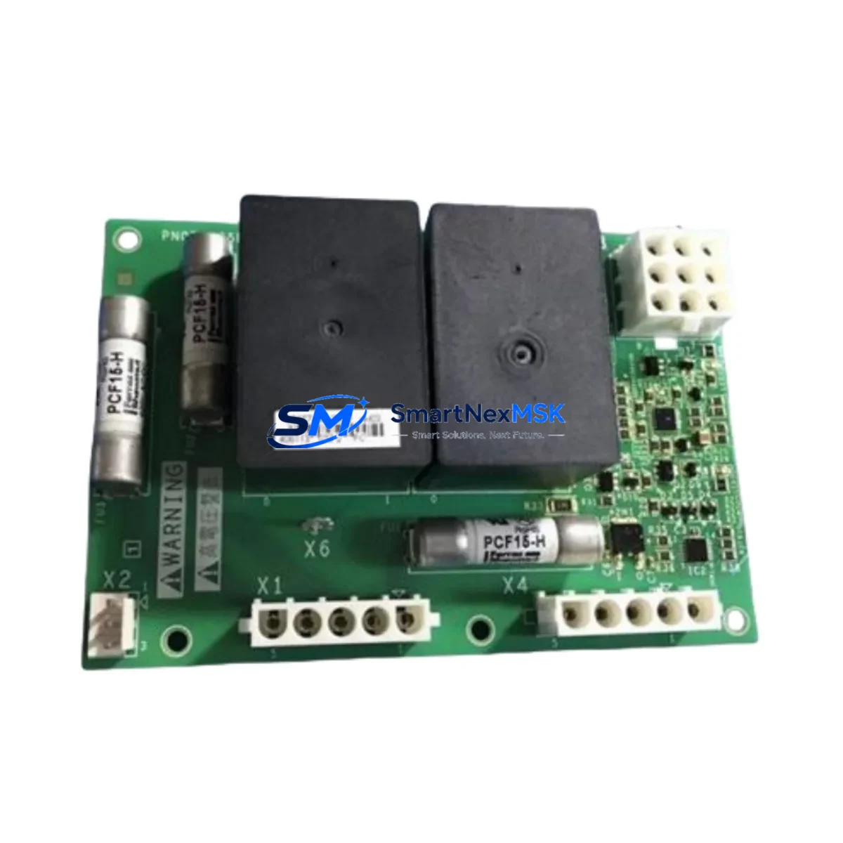
Schneider PN072546P702 Retrofit-Ready Drive Control Board: Compatible Upgrade for Altivar Control Systems
The Schneider Electric PN072546P702 is a retrofit-ready drive control board engineered for seamless integration into existing Altivar variable frequency drive (VFD) platforms. As legacy Altivar units reach end-of-life or become increasingly difficult to source, the PN072546P702 provides a verified drop-in upgrade path that preserves original wiring layouts, communication configurations, and control logic — minimizing engineering rework and unplanned downtime during system modernization.
This board is designed for industrial environments where continuity of operation is non-negotiable. Whether you are replacing a failed control board in an Altivar 61, Altivar 71, or transitioning from an older Altivar 28 or Altivar 58 platform, the PN072546P702 supports the terminal mapping and parameter structure that field engineers rely on during live-line changeovers. Its compact form factor and standardized backplane interface allow installation within existing control cabinet footprints without requiring panel modifications.
Upgrade Compatibility Table
| Parameter | Details |
|---|---|
| Compatible Series | Altivar 61, Altivar 71, Altivar 28, Altivar 58 |
| Backplane Interface | Standard Altivar control board slot (direct replacement) |
| Communication Protocols | Modbus RTU, CANopen, optional Profibus DP via add-on card |
| Terminal Wiring | Compatible with original ATV terminal block layout |
| Installation Requirement | No panel modification required; fits existing DIN rail / cabinet mount |
| Parameter Migration | Supports parameter upload/download via SoMove or PowerSuite software |
| Commissioning Tool | Compatible with Schneider SoMove, VW3A8104 programming cable |
| Retrofit Recommendation | Verify firmware version compatibility before power-on |
| Debugging Focus | I/O address mapping, speed reference source, fault relay wiring |
| Warranty | 12 months from date of shipment |
Retrofit Planning for Existing Automation Systems
A successful retrofit using the PN072546P702 begins well before the board arrives on-site. Engineers should document the existing Altivar drive configuration using SoMove or the VW3A8104 programming cable to export all parameter sets, including acceleration/deceleration ramps, motor nameplate data, PID loop settings, and fault history. This backup ensures that if the replacement board requires parameter re-entry, the process is fast and accurate.
Power supply verification is a critical pre-installation step. Confirm that the 24 VDC control supply feeding the drive’s logic section meets the PN072546P702’s input tolerance range. In multi-drive panels where a shared TSXPSY2600M or similar Schneider power supply module feeds multiple control boards, verify that the aggregate load remains within rated capacity after the board swap.
Terminal block wiring should be photographed and labeled before removal. The PN072546P702 maintains the standard Altivar control terminal layout, but engineers should cross-reference the AI1, AI2, AO1, DI1–DI6, and relay output terminals against the original wiring diagram. In systems where a Magelis HMIGTO or XBTGT HMI panel communicates with the drive over Modbus RTU via the RJ45 port, the communication parameters — baud rate, parity, station address — must be re-entered after board replacement to restore HMI screen functionality.
For installations using a CANopen network with a Schneider TM5 or Advantys STB I/O island, confirm that the node address and baud rate settings on the PN072546P702 match the original drive’s CANopen configuration. If the system uses a Profibus DP network, the optional VW3A3607 Profibus card must be transferred from the old board or a new card ordered alongside the PN072546P702.
Rack and backplane integrity should be inspected during the changeover. In multi-drive installations sharing a common Altivar cabinet with a Modicon M340 or M580 PLC rack, ensure that the backplane connectors are free of corrosion and that the rack’s power distribution is stable before inserting the new board. If the system includes a TeSys D or TeSys K motor starter in the same panel, verify that the starter’s control wiring does not share a common ground path that could introduce noise into the drive’s analog inputs after the retrofit.
Downtime Control During System Migration
Minimizing production interruption during a drive control board replacement requires a structured changeover plan. Begin by scheduling the swap during a planned maintenance window and preparing a rollback procedure in case the replacement board requires additional configuration time. Export the full parameter set from the existing drive before shutdown using SoMove connected via the VW3A8104 cable, and store the backup file on a local engineering laptop as well as a network share.
During the physical swap, use anti-static precautions and avoid touching the board’s edge connectors. After seating the PN072546P702, restore power to the control circuit only — do not enable the main power stage until all parameter values have been verified and the HMI communication link has been confirmed active. Use the drive’s keypad or SoMove to step through the quick-start wizard, re-entering motor nameplate data and confirming the speed reference source (AI1 analog, Modbus, or fieldbus).
Perform a no-load test run at low speed before reconnecting the mechanical load. Monitor the drive’s output current, DC bus voltage, and fault register during the initial run. Once stable operation is confirmed, restore the full load and verify that the Magelis HMI or SCADA system is receiving correct drive status feedback — run/stop state, output frequency, and fault codes — before signing off on the retrofit.
Retrofit Support FAQ
Q1: Is the PN072546P702 a direct replacement for the original Altivar 71 control board?
A: Yes. The PN072546P702 is designed as a form-fit-function replacement for the Altivar 71 control board. Terminal wiring, backplane interface, and communication port locations are compatible with the original installation. Parameter re-entry via SoMove is required after board replacement.
Q2: Will my existing Modbus RTU wiring and HMI configuration work after the swap?
A: In most cases, yes. The PN072546P702 supports Modbus RTU over the standard RJ45 port. You will need to re-enter the station address, baud rate, and parity settings to match your existing network configuration. HMI screens on Magelis or third-party panels will resume normal operation once communication parameters are restored.
Q3: What testing is performed before shipment?
A: Each PN072546P702 unit undergoes functional power-on testing, communication port verification, and parameter read/write validation before dispatch. Units are shipped with a test report confirming board functionality. A 12-month warranty covers defects in materials and workmanship from the date of shipment.
Q4: Can I use my existing VW3A8104 programming cable for commissioning?
A: Yes. The PN072546P702 is compatible with the standard Schneider VW3A8104 USB-to-RJ45 programming cable and SoMove software. No additional adapters are required for parameter upload, download, or firmware verification.
© 2026 SMARTNEXMSK. All rights reserved.
Original Source: https://smartnexmsk.com
Contact: sales@smartnexmsk.com | +86 18259474341