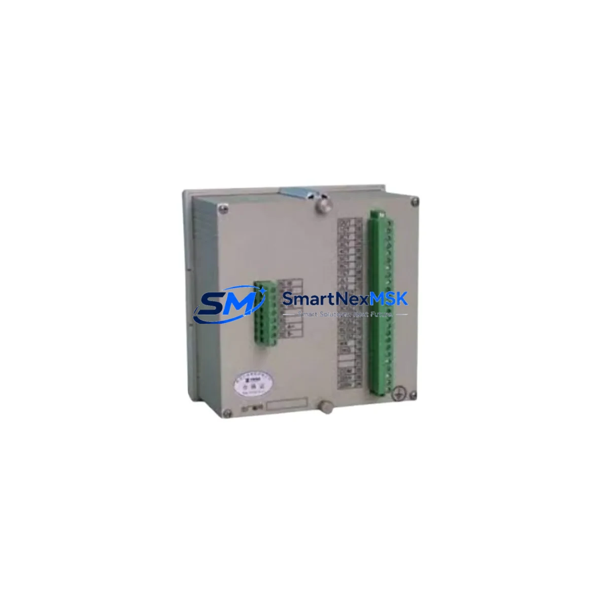
Shaanxi Zhongguan DWK3-110CD Spare for DWK3 Automation: Spare Parts Replacement & Industrial Downtime Risk Control
The Shaanxi Zhongguan DWK3-110CD is an original reactive power compensation controller designed for continuous-duty industrial power distribution systems. As a maintenance-ready spare, the DWK3-110CD plays a critical role in keeping low-voltage power factor correction (PFC) panels operational, preventing reactive power penalties, and protecting downstream electrical equipment from voltage instability. Whether you are managing a planned overhaul, responding to an unscheduled fault, or building a strategic spare parts inventory for aging power distribution infrastructure, the DWK3-110CD is a direct, verified replacement for the DWK3 Series platform.
Sourced directly from the original manufacturer — Shaanxi Zhongguan Electric Control Co., Ltd — every unit shipped by SMARTNEXMSK undergoes pre-shipment functional verification, ensuring that the controller arrives ready for immediate installation. With a 12-month warranty and documented compatibility with the DWK3 Series compensation panels, this spare part supports both emergency replacement and long-term asset lifecycle management.
Spare Maintenance Table
| Parameter | Specification |
|---|---|
| SKU / Model | DWK3-110CD |
| Brand | Shaanxi Zhongguan Electric Control Co., Ltd |
| Series | DWK3 Series |
| Product Type | Reactive Power Compensation Controller |
| Rated Voltage | 110V AC (CD variant — confirm panel nameplate before installation) |
| Application | Low-voltage reactive power compensation panels, PFC cabinets, industrial power distribution |
| Compatibility | DWK3 Series compensation panels; verify terminal layout and CT input ratio before replacement |
| Origin | China (CN) — Shaanxi Province |
| Installation | Panel-mount, DIN rail compatible; standard 35mm rail recommended |
| Operating Environment | Indoor industrial environments; ambient temperature 0–45°C, humidity ≤85% RH non-condensing |
| Maintenance Recommendation | Inspect CT wiring, capacitor bank contactors, and fuse holders at each scheduled maintenance interval |
| Pre-Shipment Testing | Functional verification performed before dispatch |
| Warranty | 12 Months from date of shipment |
| Lead Time | In-stock units ship within 1–3 business days |
Maintenance Planning for Continuous Operation
When replacing the DWK3-110CD controller in a reactive power compensation panel, a thorough maintenance engineer will not limit the inspection to the controller alone. The DWK3-110CD interfaces directly with the panel’s current transformer (CT) input circuit, capacitor bank switching contactors, and the main power bus — all of which should be evaluated during the same maintenance window to prevent repeat failures and maximize uptime.
Begin by inspecting the CT secondary wiring and terminal blocks: loose or corroded CT connections are a leading cause of controller misreading and false switching events. Next, check the capacitor bank contactors (typically AC contactors rated for capacitive switching duty) for contact wear, coil resistance, and mechanical operation — worn contactors are frequently the root cause of DWK3-110CD controller faults rather than the controller itself. If the panel uses capacitor protection fuses or fast-blow fuse holders, verify fuse continuity and replace any that show signs of thermal stress.
For panels integrated into a broader power distribution system, also inspect the incoming power supply module feeding the controller’s auxiliary voltage circuit. Voltage fluctuations outside the controller’s rated input range can cause erratic compensation behavior or premature component failure. If the compensation panel communicates with a building management system or SCADA via a RS-485 communication module or Modbus RTU interface, verify the communication cable shielding and termination resistor integrity at the same time.
In control cabinets where the DWK3-110CD operates alongside power quality meters, harmonic filters, or signal isolators, confirm that the CT ratio settings programmed into the replacement controller match the original configuration exactly — a mismatch will cause the compensation system to over- or under-correct, potentially tripping upstream protection relays. Where surge protection devices (SPDs) are installed on the panel’s incoming supply, check their status indicators and replace any that have operated, as a degraded SPD offers no protection to the new controller.
Finally, if the compensation panel is part of an older system approaching end-of-life, consider stocking a second DWK3-110CD unit alongside spare contactors and a set of replacement capacitor bank fuses as a minimum viable spare kit. This approach significantly reduces mean time to repair (MTTR) during unscheduled outages and supports a proactive maintenance strategy aligned with IEC 60831 capacitor bank maintenance guidelines.
Site Replacement Workflow
Step 1 — Isolation & Lockout: De-energize the compensation panel at the incoming MCCB and apply lockout/tagout (LOTO) per site safety procedures. Verify absence of voltage on all busbars before opening the panel door.
Step 2 — Document Existing Configuration: Before removing the old DWK3-110CD, photograph or record all parameter settings displayed on the controller (CT ratio, number of compensation steps, switching delay, target power factor). These settings must be re-entered on the replacement unit.
Step 3 — Wiring Verification: Label all CT input, voltage sensing, and contactor output wires before disconnection. Cross-reference against the panel wiring diagram. Inspect terminal block condition and replace any damaged terminals before reconnecting.
Step 4 — Install DWK3-110CD Replacement: Mount the new controller in the original panel cutout or DIN rail position. Reconnect all wiring per the original diagram, ensuring CT polarity is maintained. Incorrect CT polarity will cause the controller to switch capacitors in the wrong direction, worsening power factor.
Step 5 — Parameter Programming: Power up the controller and enter all previously recorded parameters. Confirm CT ratio, target power factor (typically 0.95 lagging), number of active steps, and switching delay settings match the original configuration.
Step 6 — Functional Test: Restore power to the panel under load and observe the controller’s step switching behavior over a 10–15 minute period. Verify that the power factor reading on the controller display or upstream power quality meter improves to the target value. Check for any alarm or fault indicators.
Step 7 — Documentation & Handover: Update the panel maintenance log with the replacement date, new controller serial number, and parameter settings. Retain the original unit for failure analysis if required.
This workflow is applicable to both like-for-like DWK3-110CD replacements and upgrades from earlier DWK3 Series variants. The standardized DWK3 platform interface ensures backward compatibility across the series, minimizing engineering time during replacement.
Spare Parts Support FAQ
Q1: Is the DWK3-110CD a direct replacement for other DWK3 Series controllers?
The DWK3-110CD is designed for 110V AC auxiliary supply applications within the DWK3 Series platform. Other DWK3 variants may differ in rated voltage (e.g., 220V AC versions) or the number of compensation output steps. Always verify the auxiliary voltage rating and step count on the original controller’s nameplate before ordering a replacement to ensure full compatibility.
Q2: How does SMARTNEXMSK verify the DWK3-110CD before shipment?
Every DWK3-110CD unit undergoes a pre-shipment functional check covering power-on self-test, display operation, and output relay actuation. Units that do not pass verification are not dispatched. Each shipment includes a test record, and all units are covered by a 12-month warranty from the date of shipment.
Q3: What is the recommended spare parts inventory strategy for DWK3-110CD?
For facilities operating multiple reactive power compensation panels, we recommend maintaining at least one DWK3-110CD controller in stock per five panels, alongside a set of spare capacitor bank contactors and fuses. For critical production environments where power factor penalties or downtime costs are high, a one-to-one spare ratio per panel is advisable. SMARTNEXMSK supports long-term supply agreements to ensure consistent availability.
Q4: What should I check if the replacement DWK3-110CD does not improve power factor after installation?
If the replacement controller does not achieve the target power factor, the most common causes are: incorrect CT ratio programming, reversed CT polarity, failed capacitor bank contactors not responding to switching commands, open-circuit capacitor fuses, or degraded capacitor banks that no longer provide rated reactive power output. Systematically verify each of these elements before concluding that the controller itself is at fault. SMARTNEXMSK’s technical support team is available to assist with fault diagnosis.
© 2026 SMARTNEXMSK. All rights reserved.
Original Source: https://smartnexmsk.com
Contact: [email protected] | +86 18259474341