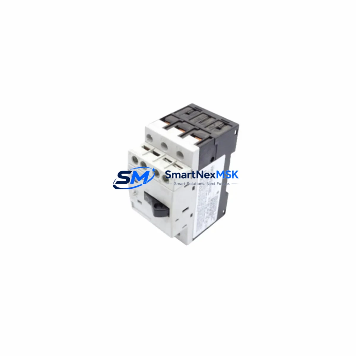
Siemens 3VU1301-1MJ00 Maintenance-Ready Spare for SIRIUS 3VU Automation
The Siemens 3VU1301-1MJ00 is a compact motor protection circuit breaker from the SIRIUS 3VU series, engineered for reliable overload and short-circuit protection in industrial motor control applications. As a maintenance-ready spare, this unit is sourced as an original component and is fully tested prior to shipment, ensuring immediate drop-in replacement capability for aging or failed units in your control cabinet. Holding verified stock of the 3VU1301-1MJ00 is a proven strategy for minimizing unplanned downtime in production lines, pump stations, conveyor systems, and HVAC-integrated automation environments.
For maintenance engineers managing legacy SIRIUS-based motor control centers (MCCs), the 3VU1301-1MJ00 represents a critical line item in any preventive maintenance BOM. Its compact DIN-rail mounting profile and standardized terminal pitch make it directly interchangeable with earlier 3VU variants, reducing installation time during emergency callouts. Procurement engineers can rely on our 12-month warranty and pre-shipment functional verification to meet site acceptance requirements without additional incoming inspection overhead.
Spare Maintenance Table
| Parameter | Specification / Detail |
|---|---|
| Part Number / SKU | 3VU1301-1MJ00 |
| Brand | Siemens |
| Series | SIRIUS 3VU |
| Product Type | Motor Protection Circuit Breaker |
| Rated Current Range | 6.3–10 A (adjustable) |
| Poles | 3-pole |
| Mounting | DIN rail (35 mm) / screw mounting |
| Tripping Class | Class 10 (thermal-magnetic) |
| Short-Circuit Breaking Capacity | Up to 100 kA (with fuse backup) |
| Ambient Temperature | -25 °C to +60 °C |
| Degree of Protection | IP20 (terminal area) |
| Country of Origin | Germany |
| Compatibility | SIRIUS 3VU series; replaces earlier 3VU1 variants |
| Application Environment | Motor control centers, pump panels, conveyor drives, HVAC automation |
| Maintenance Recommendation | Inspect trip mechanism and terminal torque annually; replace at first sign of contact wear or nuisance tripping |
| Warranty | 12 months from date of shipment |
| Pre-Shipment Testing | Functional verification performed on every unit |
Maintenance Planning for Continuous Operation
When replacing the 3VU1301-1MJ00 in the field, a thorough inspection of the surrounding control circuit is essential to prevent repeat failures and ensure system integrity. Maintenance engineers should begin by verifying the upstream power supply module — such as a Siemens SITOP PSU100S or equivalent 24 VDC regulated supply — to confirm stable input voltage within tolerance before re-energizing the motor branch.
The motor contactor paired with the 3VU1301-1MJ00 — typically a Siemens 3RT2 series contactor — should be inspected for contact wear, coil resistance, and auxiliary contact continuity. Worn contactor contacts are a common root cause of nuisance tripping in motor protection circuits and should be replaced proactively during the same maintenance window. Similarly, the associated 3RH2 auxiliary contactor relay used for interlocking or signaling should be tested for coil pull-in voltage and contact resistance.
Terminal blocks and wiring within the motor feeder circuit deserve close attention. Loose or corroded terminals on Phoenix Contact or Weidmüller-style terminal strips can introduce resistance that mimics overload conditions, causing false trips. Re-torque all power terminals to manufacturer specification and inspect for discoloration or insulation damage.
If the motor branch feeds a variable frequency drive (VFD) or soft starter, verify that the drive’s output current settings are correctly configured to avoid nuisance tripping of the 3VU1301-1MJ00 during acceleration ramps. For systems using a Siemens SIMATIC S7-300 or S7-1200 PLC for motor sequencing, confirm that the digital output module (e.g., SM 322 or SM 1222) controlling the contactor coil is functioning correctly and that the I/O address mapping remains intact after any CPU replacement or firmware update.
Communication modules such as the CP 343-1 or CP 1243-1 used for PROFINET or Industrial Ethernet connectivity should be checked for link status and cyclic data exchange health, particularly if the motor protection event was logged as a process alarm. Signal isolators in the feedback circuit — for example, Phoenix Contact MINI MCR signal conditioners — should be verified for correct output scaling if analog motor current feedback is used for monitoring.
Finally, inspect any associated fuse holders (e.g., Siemens 3NW series) and fuse links in the motor branch for continuity and correct rating. Maintaining a cabinet-level spare kit that includes the 3VU1301-1MJ00, a matched 3RT2 contactor, spare fuse links, and a set of terminal block jumpers significantly reduces mean time to repair (MTTR) during unplanned outages.
Site Replacement Workflow
Step 1 — Isolation & Lockout/Tagout: De-energize the motor branch at the upstream isolator. Apply LOTO per site safety procedure. Verify absence of voltage at the 3VU1301-1MJ00 line terminals using a calibrated voltage tester.
Step 2 — Documentation: Photograph the existing wiring layout and record the current trip setting dial position before removal. Note the trip class and any auxiliary contact wiring (e.g., 3VU9 auxiliary switch block if fitted).
Step 3 — Removal: Loosen all terminal screws and remove conductors. Unclip the unit from the DIN rail or remove mounting screws. If an auxiliary switch block (3VU9 series) is attached, detach it carefully for reuse on the replacement unit.
Step 4 — Installation of 3VU1301-1MJ00: Clip the new unit onto the DIN rail. Reattach any auxiliary switch block. Reconnect all conductors per the documented layout, torquing terminals to specification (typically 2.5–3 Nm for power terminals).
Step 5 — Setting & Verification: Set the overload trip dial to the motor’s rated current (FLA). Confirm the trip class selector (if present) matches the original setting. Perform a manual trip test using the test button to verify mechanism operation.
Step 6 — Re-energization & Commissioning: Remove LOTO, re-energize the branch, and perform a no-load motor start. Monitor current draw and confirm the PLC or SCADA system receives the correct motor run feedback signal. Log the replacement in the site maintenance record.
This workflow is compatible with direct replacement of earlier 3VU1 variants and supports system continuity without requiring PLC program changes or re-parameterization of the motor control circuit.
Spare Parts Support FAQ
Q1: What is the warranty coverage for the 3VU1301-1MJ00?
All units carry a 12-month warranty from the date of shipment. Each unit undergoes functional verification prior to dispatch. Warranty claims are supported with replacement or refund based on confirmed defect assessment.
Q2: How do I confirm compatibility with my existing SIRIUS 3VU installation?
The 3VU1301-1MJ00 is directly compatible with standard SIRIUS 3VU series mounting accessories, auxiliary switch blocks (3VU9 series), and DIN rail profiles. Verify the rated current range (6.3–10 A) matches your motor’s FLA. For legacy 3VU1 installations, the physical footprint and terminal pitch are interchangeable.
Q3: Can I order in bulk for a spare parts inventory program?
Yes. We support blanket orders and scheduled releases for maintenance inventory programs. Bulk pricing and lead-time commitments are available. Contact our sales team to discuss consignment stock or VMI arrangements for high-criticality sites.
Q4: What pre-shipment checks are performed before delivery?
Every 3VU1301-1MJ00 unit is subject to functional verification including trip mechanism actuation, terminal continuity check, and visual inspection for physical damage. Units are packed in anti-static, shock-resistant packaging to maintain condition during transit.
© 2026 SMARTNEXMSK. All rights reserved.
Original Source: https://smartnexmsk.com
Contact: [email protected] | +86 18259474341