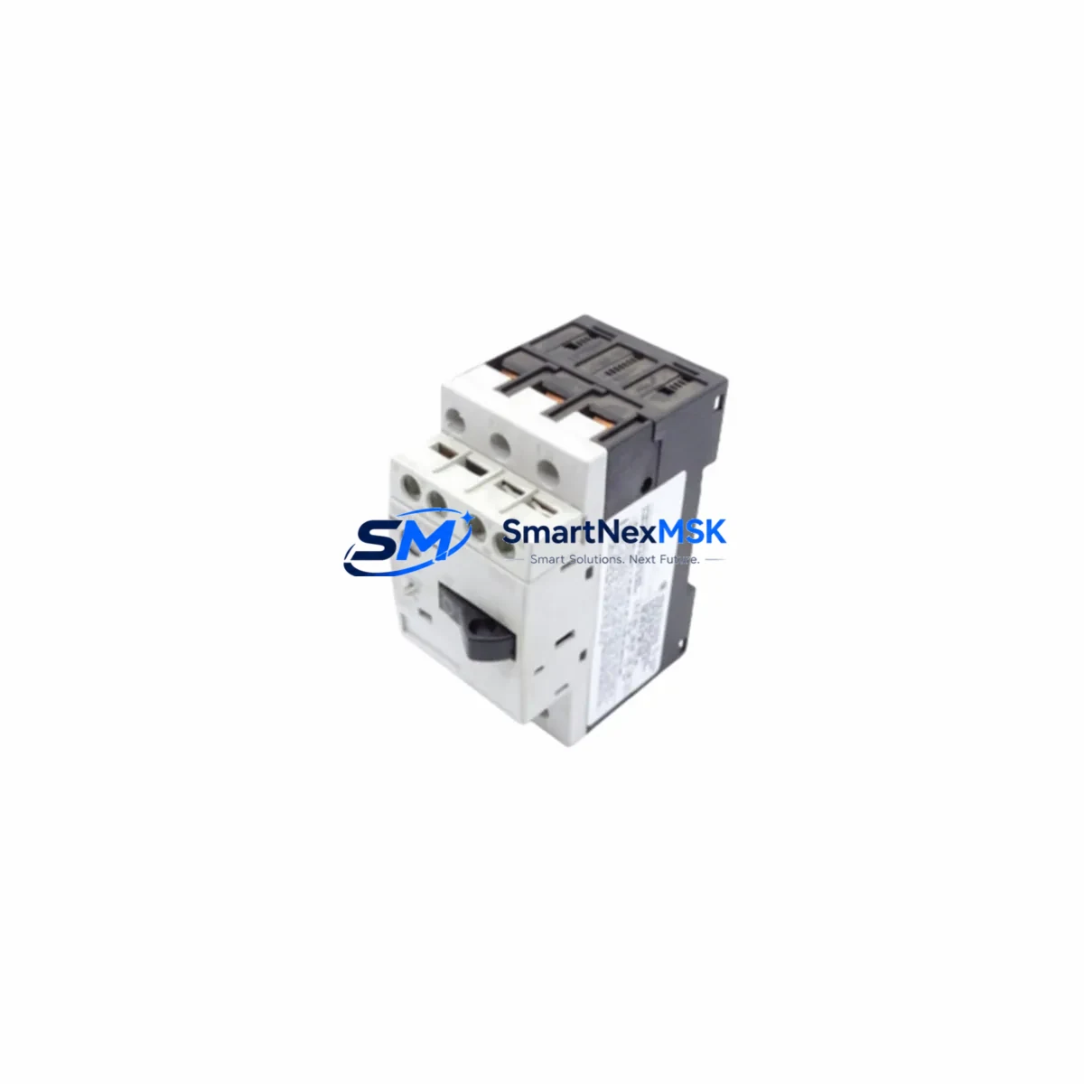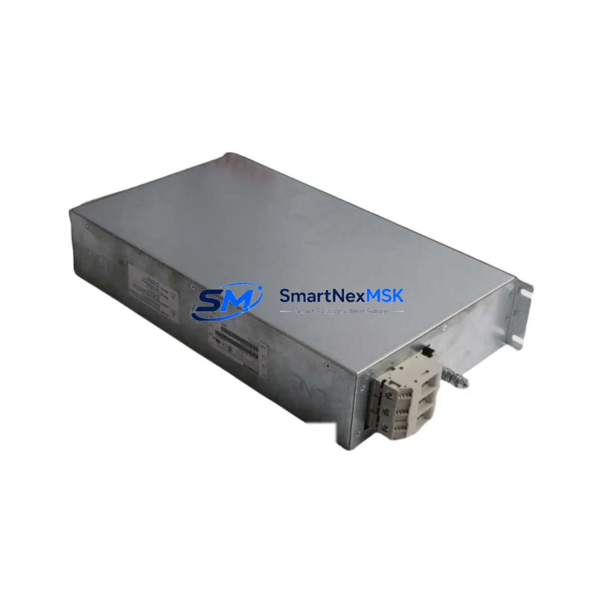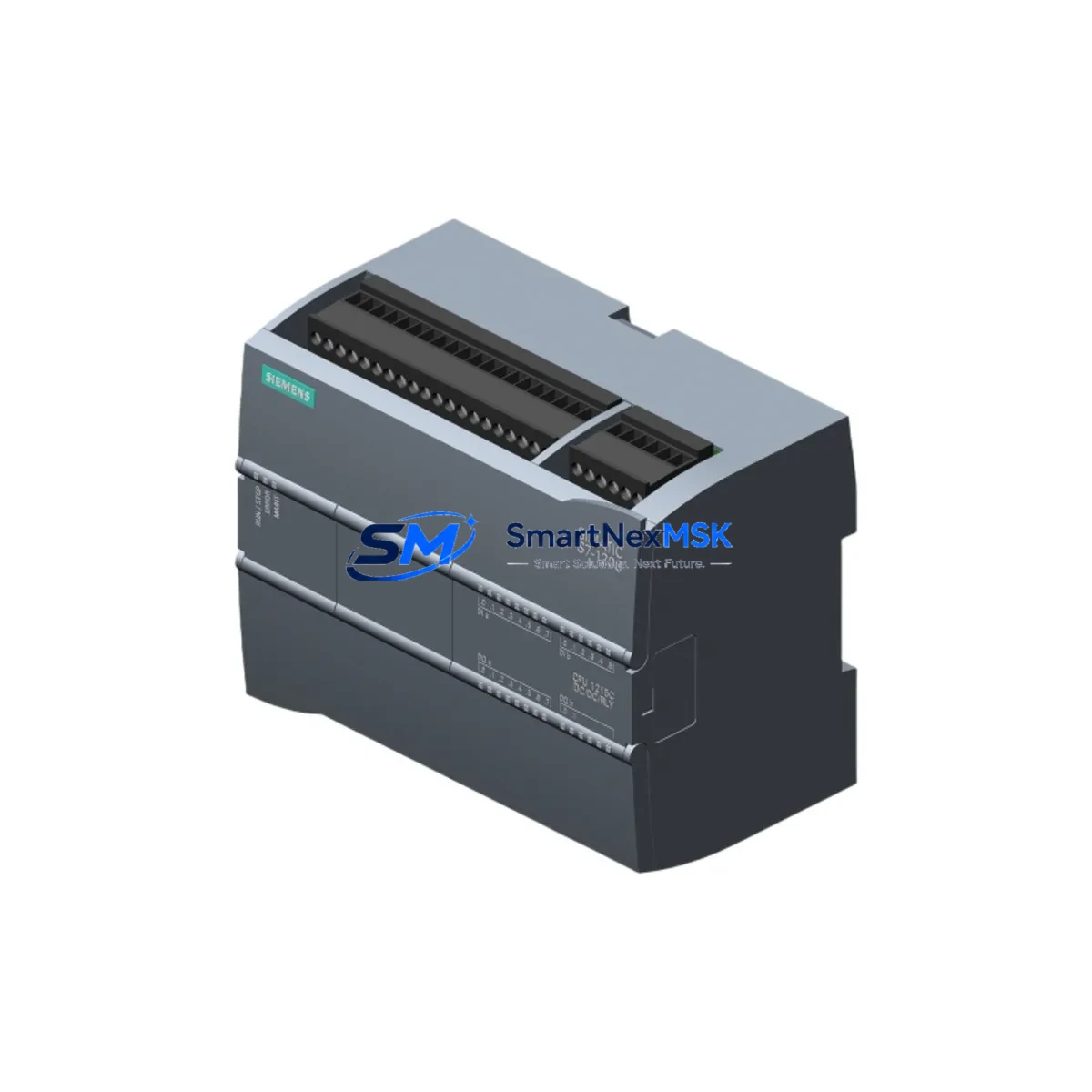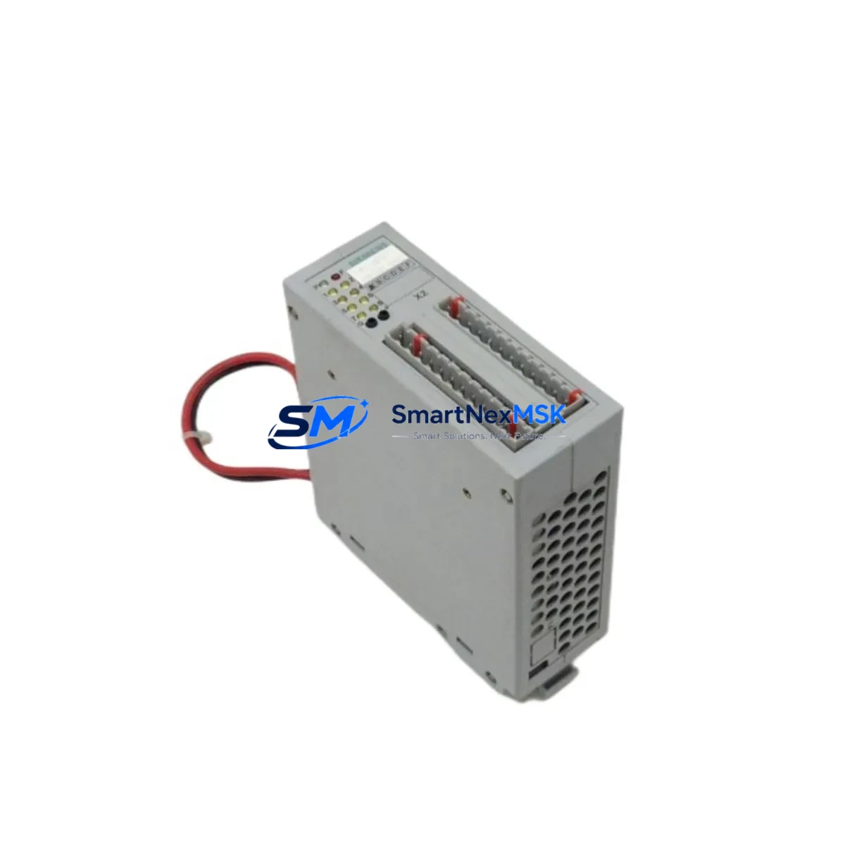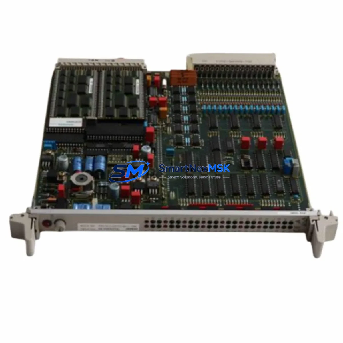
Siemens 7UT5121-4CB01-0AA0/LL Retrofit-Ready Differential Protection Relay for SIPROTEC 4 Control Systems
The Siemens 7UT5121-4CB01-0AA0/LL is a transformer differential protection relay from the SIPROTEC 4 platform, engineered for high-reliability protection of power transformers, generators, and motors in industrial and utility substation environments. As legacy SIPROTEC 3 and early SIPROTEC 4 installations reach end-of-service life, the 7UT5121-4CB01-0AA0/LL has become a primary retrofit target for engineers modernizing aging protection schemes without full panel replacement.
This unit supports IEC 61850 GOOSE messaging and serial communication via PROFIBUS or RS-485, making it compatible with both legacy SCADA architectures and modern digital substation frameworks. When replacing an older 7UT512 or 7UT513 variant, engineers must verify the CT secondary rating (1A or 5A), confirm the binary input/output terminal mapping against the existing wiring diagram, and validate the protection function parameter set using DIGSI 4 software before energizing the replacement unit.
For sites running SIPROTEC 4 chassis with the 7XV5100 communication module or 7SJ62/7SJ64 overcurrent relays in the same protection panel, the 7UT5121-4CB01-0AA0/LL integrates directly into the existing IEC 61850 station bus without requiring gateway reconfiguration. The relay’s 24-pin rear terminal block follows the standard SIPROTEC 4 footprint, allowing direct substitution in most 19-inch rack or flush-mount enclosures.
Customers sourcing this unit for emergency sparing or planned outage replacement should confirm the firmware version compatibility with their existing DIGSI 4 project file. Units shipped from our inventory are tested for power-on self-diagnostics, output relay continuity, and communication port response prior to dispatch. Each unit ships with a 12-month warranty covering manufacturing defects and functional failures under normal operating conditions.
Upgrade Compatibility Table
| Parameter | Details |
|---|---|
| SKU / Order Number | 7UT5121-4CB01-0AA0/LL |
| Series | Siemens SIPROTEC 4 |
| Function | Transformer Differential Protection (87T) |
| Replaces / Compatible With | 7UT512, 7UT513, 7UT5125, early SIPROTEC 4 variants |
| Rear Terminal Interface | 24-pin SIPROTEC 4 standard terminal block |
| CT Input Rating | 1A / 5A selectable — confirm before installation |
| Communication Ports | RS-485 (PROFIBUS), IEC 61850 (with 7XV5100 module) |
| Configuration Software | DIGSI 4 (v4.82 or later recommended) |
| Power Supply | 24–250 V DC / 100–230 V AC (confirm auxiliary voltage) |
| Mounting | 19-inch rack or flush panel, SIPROTEC 4 standard |
| Firmware Compatibility | Verify against existing DIGSI 4 project file |
| Pre-shipment Testing | Power-on diagnostics, output relay continuity, comms port check |
| Warranty | 12 Months — manufacturing defects and functional failures |
| Origin | Germany |
Retrofit Planning for Existing Automation Systems
A successful retrofit of the 7UT5121-4CB01-0AA0/LL into an existing protection panel begins well before the scheduled outage window. The first step is a full audit of the existing protection scheme: collect the original DIGSI 4 project file, the panel wiring diagram, and the CT/VT nameplate data. If the site is running a 7UT512 or 7UT513 as the primary differential element, the terminal assignment is largely compatible, but engineers should cross-check binary input voltage levels — some older installations use 48 V DC logic while the replacement unit may default to 110 V DC thresholds.
For panels that also house a 7SJ62 or 7SJ64 overcurrent relay as backup protection, the IEC 61850 GOOSE dataset configuration must be reviewed to ensure the new 7UT5121 publishes the correct logical node addresses expected by the bay controller or 7SC80 substation controller. If the site uses a 7XV5100 Ethernet communication module for station bus connectivity, confirm that the module firmware supports the IEC 61850 edition used in the project.
Power supply capacity is a critical checkpoint. The existing 7XV5662 or equivalent DC distribution board must supply sufficient current for the replacement relay’s auxiliary circuit. Measure the actual DC bus voltage under load before connecting the new unit. If the panel also contains a 7KE85 fault recorder or 7UM62 generator protection relay sharing the same DC rail, calculate the total burden to avoid nuisance trips on the DC MCB during energization.
For sites migrating from serial PROFIBUS communication to IEC 61850, the 7UT5121-4CB01-0AA0/LL supports both protocols simultaneously during the transition period, allowing the SCADA system to be reconfigured without interrupting protection coverage. The 7XV5100 communication module handles the Ethernet interface, while the existing RS-485 link to the 6MD66 bay control unit can remain active until the migration is complete.
Before the outage, prepare a pre-tested DIGSI 4 parameter set loaded onto a laptop with the correct firmware version. Bring a 7XV5100 spare module, a set of SIPROTEC 4 terminal connectors, and a calibrated secondary injection test set. After physical installation, perform a secondary injection test on all differential and restraint inputs to verify the slope characteristic and pickup thresholds match the original settings. Confirm all binary outputs operate the correct trip and alarm circuits before restoring the transformer to service.
Downtime Control During System Migration
Minimizing outage duration during a SIPROTEC 4 relay replacement requires a structured pre-outage preparation protocol. The most effective approach is to pre-configure the replacement 7UT5121-4CB01-0AA0/LL offline using DIGSI 4, loading the parameter set from the existing project file and adjusting only the parameters that differ between the old and new hardware variants. This eliminates on-site programming time and reduces the risk of parameter entry errors under time pressure.
Maintain a parallel protection path wherever possible. If the substation design includes a backup overcurrent relay such as the 7SJ64 or a busbar protection scheme via the 7SS52, confirm that these elements remain in service and correctly configured throughout the differential relay replacement. Coordinate with the control room to ensure that the SCADA alarm suppression is active only for the specific relay being replaced, so that any anomaly on adjacent feeders is still annunciated.
Document the existing terminal wiring with photographs before disconnecting any conductors. Label each CT and VT secondary wire individually. Use the SIPROTEC 4 standard terminal block’s plug-in connector design to your advantage — the rear connector can be pre-wired to the new relay on the bench and plugged in as a single assembly during the outage, cutting live-panel wiring time to near zero. After reconnection, perform a functional check of all binary inputs and outputs using the DIGSI 4 test mode before issuing the relay into service. A well-prepared team can complete the physical swap, secondary injection test, and functional verification within a four-hour planned outage window.
Retrofit Support FAQ
Q1: Is the 7UT5121-4CB01-0AA0/LL a direct drop-in replacement for the 7UT512 or 7UT513?
In most installations, yes — the rear terminal block and mounting footprint are compatible with the SIPROTEC 4 standard. However, you must verify the CT secondary rating (1A vs 5A), auxiliary supply voltage, and binary input threshold voltage before installation. Load the existing DIGSI 4 parameter file and review any hardware-dependent settings before energizing the replacement unit.
Q2: What software is required to configure and commission this relay?
Siemens DIGSI 4 (version 4.82 or later is recommended) is required for parameter upload, functional testing, and event log retrieval. Ensure your laptop has the correct USB-to-serial or Ethernet adapter for the relay’s front communication port. If the site uses IEC 61850, the DIGSI 4 IEC 61850 System Configurator tool is also required to define the GOOSE dataset and logical node mapping.
Q3: What does the 12-month warranty cover, and what is the claim process?
The 12-month warranty covers manufacturing defects and functional failures under normal operating conditions from the date of shipment. It does not cover damage from incorrect installation, overvoltage, or physical impact. To initiate a warranty claim, contact [email protected] with the order number, a description of the fault, and any available DIGSI 4 event log exports. Replacement or repair will be arranged within 5 business days of claim confirmation.
Q4: Can this unit be tested before installation to verify it is functional?
Yes. Each unit undergoes a pre-shipment functional test covering power-on self-diagnostics, output relay continuity, and communication port response. Customers may also perform their own secondary injection test using a calibrated relay test set before installation. We recommend performing a full differential characteristic test (slope 1, slope 2, and inrush restraint) to confirm the unit matches the expected protection curve before energizing the primary equipment.
© 2026 SMARTNEXMSK. All rights reserved.
Original Source: https://smartnexmsk.com
Contact: [email protected] | +86 18259474341