
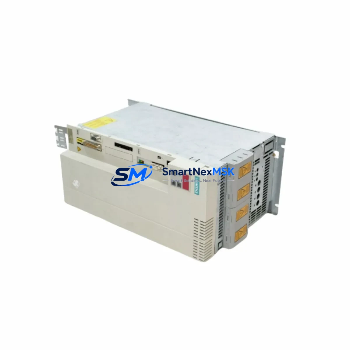
Siemens 6ES7023-8TP60-Z Retrofit-Ready Interface Module for S7-300 Control Systems
The Siemens 6ES7023-8TP60-Z is a SIMATIC S7-300 series Interface Module (IM) designed for rack expansion and inter-rack communication in distributed automation architectures. As legacy S7-300 systems approach end-of-life and spare parts become increasingly scarce, the 6ES7023-8TP60-Z remains one of the most sought-after retrofit components for engineers tasked with modernizing existing control cabinets without full system replacement. This module enables seamless expansion rack connectivity, preserving the original program logic, I/O addressing, and HMI screen configurations while extending the operational life of the installed base.
SMARTNEXMSK maintains verified stock of the 6ES7023-8TP60-Z with full functional testing prior to shipment. Each unit ships with a 12-month warranty covering hardware defects and operational failures under normal industrial conditions.
Upgrade Compatibility Table
| Parameter | Details |
|---|---|
| SKU / Order Number | 6ES7023-8TP60-Z (Z-G91-K80) |
| Series | SIMATIC S7-300 |
| Module Type | Interface Module (IM) — Send/Receive |
| Backplane Interface | S7-300 standard DIN rail backplane bus |
| Installation | DIN rail, standard S7-300 rack slot |
| Communication | Rack-to-rack expansion via IM send/receive pair |
| Replaces / Compatible With | 6ES7023-8TP60-0AB0 and equivalent IM send modules |
| Power Supply Requirement | Supplied via backplane bus (no external 24 VDC required) |
| Retrofit Recommendation | Verify IM pair addressing and rack slot assignment before installation |
| Commissioning Note | Re-download hardware configuration via STEP 7 or TIA Portal after swap |
| Warranty | 12 Months — covers hardware defects under normal operating conditions |
Retrofit Planning for Existing Automation Systems
Retrofitting an S7-300 expansion rack begins well before the replacement module arrives on site. Engineers must audit the existing rack layout, confirm the CPU model (such as the CPU 315-2 DP or CPU 317-2 PN/DP), and verify that the power supply module — typically a PS 307 5A or PS 307 10A — can support the additional current draw introduced by the new IM and any associated I/O modules in the expansion rack.
The 6ES7023-8TP60-Z functions as the send-side IM in a paired configuration. The corresponding receive-side module in the expansion rack — commonly the 6ES7153-1AA03-0XB0 ET 200M IM or a compatible IM 360/361 receive module — must be verified for firmware compatibility and slot assignment. Mismatched IM pairs are a leading cause of rack communication faults during retrofit commissioning.
Terminal wiring in the expansion rack should be documented before any module swap. Digital input modules such as the SM 321 DI 32×DC 24V and digital output modules such as the SM 322 DO 32×DC 24V/0.5A retain their terminal assignments, but the module address in the hardware configuration must be confirmed against the STEP 7 project. Analog I/O modules — for example the SM 331 AI 8×12Bit or SM 332 AO 4×12Bit — require calibration verification after the rack is re-energized.
For systems using PROFIBUS DP as the fieldbus backbone, the DP address of the expansion rack’s IM must be preserved. Any change to the DP address requires a corresponding update in the CPU’s hardware configuration and a full download. Where MPI communication links the programming device to the CPU, the MPI address and baud rate settings should be confirmed before going online. Systems that have migrated or are migrating to PROFINET should note that the 6ES7023-8TP60-Z is a backplane expansion IM and does not participate in the PROFINET network directly — PROFINET connectivity is handled at the CPU or CP 343-1 communication processor level.
HMI panels connected to the system — such as a TP700 Comfort or MP277 — typically communicate with the CPU via MPI or PROFIBUS and are unaffected by an IM swap, provided the CPU slot and rack configuration remain unchanged. However, if the retrofit involves re-racking or slot reassignment, HMI variable tables referencing absolute I/O addresses must be reviewed. Programming cables such as the PC Adapter USB A2 or MPI/DP cable should be on hand during commissioning to allow direct CPU access for hardware configuration downloads and online diagnostics.
Downtime Control During System Migration
Minimizing production downtime during an S7-300 IM replacement requires a structured pre-outage preparation phase. Before the planned maintenance window, the engineer should export the current STEP 7 or TIA Portal project, back up the CPU memory card contents, and photograph all terminal wiring in the affected rack. A printed I/O force table and current diagnostic buffer export provide a baseline for post-swap verification.
During the outage, the replacement sequence should follow: power down the rack via the PS 307 power supply, remove the defective 6ES7023-8TP60-Z, seat the replacement module in the identical slot, restore power, and immediately check the CPU diagnostic buffer for any rack communication errors. If the CPU enters STOP mode, a hardware configuration download via STEP 7 is typically required to re-establish the IM pair handshake.
Where continuous process control is critical, consider staging the replacement during a scheduled production break rather than an emergency shutdown. Pre-testing the replacement 6ES7023-8TP60-Z on a bench rack with a known-good IM receive module before deploying to the live system eliminates module-related variables from the commissioning process. SMARTNEXMSK performs functional burn-in testing on all IM modules prior to shipment, reducing the risk of DOA units reaching the field.
After the swap, verify all I/O signals against the force table, confirm HMI screen data is updating correctly, and clear the CPU diagnostic buffer before returning the system to automatic mode. Document the replacement with the module serial number, installation date, and technician sign-off for maintenance records.
Retrofit Support FAQ
Q1: Is the 6ES7023-8TP60-Z a direct drop-in replacement for the 6ES7023-8TP60-0AB0?
A: The 6ES7023-8TP60-Z with Z-option suffix (Z-G91-K80) is a factory-configured variant of the base IM send module. In most S7-300 retrofit applications it is functionally interchangeable with the standard 6ES7023-8TP60-0AB0, but engineers should confirm the Z-option configuration against the original project documentation before installation. SMARTNEXMSK can provide the module datasheet and Z-option specification on request.
Q2: Do I need to re-download the hardware configuration after replacing the IM?
A: In most cases, yes. After seating the replacement module, a hardware configuration download via STEP 7 or TIA Portal is recommended to ensure the CPU correctly recognizes the new IM and re-establishes the rack expansion link. This is especially important if the original module failed in a way that corrupted the rack communication state.
Q3: What wiring changes are required when installing the 6ES7023-8TP60-Z?
A: The 6ES7023-8TP60-Z connects to the expansion rack via the standard S7-300 IM cable (e.g., 6ES7368-3BB01-0AA0 IM cable). No terminal rewiring is required for the IM itself. All field wiring remains on the I/O module terminal blocks and is unaffected by the IM swap.
Q4: What does the 12-month warranty cover?
A: The 12-month warranty covers hardware defects and functional failures under normal industrial operating conditions. It does not cover damage resulting from incorrect installation, overvoltage, or environmental conditions outside the module’s rated specifications. Warranty claims are processed directly through SMARTNEXMSK with a standard RMA procedure.
© 2026 SMARTNEXMSK. All rights reserved.
Original Source: https://smartnexmsk.com
Contact: [email protected] | +86 18259474341



