
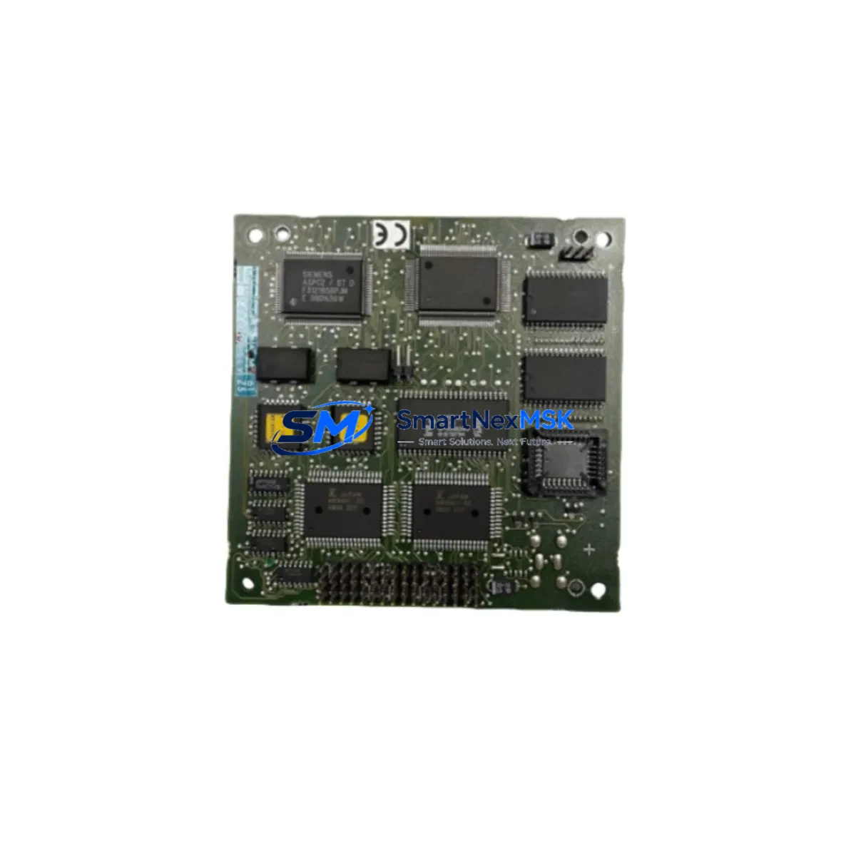
Siemens 6ES7180-0AA00-0XA0 Maintenance-Ready Spare for ET 200M Automation
The Siemens 6ES7180-0AA00-0XA0 is the IM 153-1 interface module for the ET 200M distributed I/O station, designed to connect the ET 200M rack to a PROFIBUS DP master — typically a Siemens S7-300 or S7-400 CPU. In industrial maintenance environments, this module is a critical link between the field-level I/O and the control system. A failure of this interface module results in complete loss of communication to the entire ET 200M station, causing immediate process shutdown and unplanned downtime. Holding a verified replacement unit in your spare parts inventory is the most effective strategy to minimize mean time to repair (MTTR) and protect production continuity.
SMARTNEXMSK supplies the 6ES7180-0AA00-0XA0 as an original Siemens spare part, fully tested prior to shipment, with a 12-month warranty covering functional defects. Each unit is inspected for firmware compatibility, connector integrity, and PROFIBUS address switch condition before dispatch.
Spare Maintenance Table
| Parameter | Specification |
|---|---|
| Part Number | 6ES7180-0AA00-0XA0 |
| Module Type | IM 153-1 Interface Module |
| Compatible System | ET 200M Distributed I/O, S7-300, S7-400 |
| Communication Protocol | PROFIBUS DP (up to 12 Mbit/s) |
| Max. I/O Modules per Station | Up to 8 SM modules |
| Supply Voltage | 24 V DC (via backplane bus) |
| Operating Temperature | 0 °C to +60 °C |
| Mounting | DIN rail, ET 200M rack (UR1/UR2) |
| Country of Origin | Germany |
| Condition | Original Siemens, pre-shipment tested |
| Warranty | 12 Months |
| Application | Process automation, machine control, panel replacement |
| Maintenance Recommendation | Replace immediately upon PROFIBUS fault LED or loss of DP communication; inspect PROFIBUS address switches and termination resistors during replacement |
Maintenance Planning for Continuous Operation
When a 6ES7180-0AA00-0XA0 fails or is scheduled for replacement during planned maintenance, a disciplined maintenance engineer will not stop at swapping the interface module alone. The ET 200M station is a tightly integrated assembly, and adjacent components should be inspected simultaneously to prevent repeat failures and secondary faults.
Begin with the PS 307 power supply module (e.g., 6ES7307-1BA01-0AA0) that feeds the ET 200M rack — verify output voltage stability under load, as a degraded power supply is a common root cause of intermittent IM 153-1 communication faults. Next, inspect the PROFIBUS DP cable and bus connector (e.g., 6ES7972-0BB52-0XA0) at both the IM 153-1 port and the upstream DP master port; damaged shielding or loose termination resistors frequently cause cyclic data errors that are misdiagnosed as module failures.
Within the ET 200M rack itself, check the SM 321 digital input modules and SM 322 digital output modules for blown fuse indicators, stuck relay outputs, or degraded optocoupler response. If the station includes analog I/O, inspect the SM 331 analog input and SM 332 analog output modules for drift or calibration deviation — these are often overlooked during corrective maintenance but degrade gradually in high-vibration or high-temperature environments.
For stations that include safety-rated I/O, verify the F-SM fail-safe signal modules (e.g., 6ES7326-1BK02-0AB0) are correctly parameterized after any rack power cycle. Communication-layer components such as the CP 342-5 PROFIBUS communication processor on the S7-300 CPU rack should also be checked for consistent DP cycle times using STEP 7 or TIA Portal diagnostics.
Do not overlook the terminal blocks and wiring harnesses connected to the SM modules — corroded or loose field wiring is a leading cause of I/O signal errors that surface after an IM module replacement. If the control cabinet houses signal isolators or loop-powered transmitters, verify their 24 V supply rails are within tolerance. Finally, confirm that the ET 200M rack backplane itself shows no signs of mechanical damage or oxidized bus contacts, particularly in older installations where the rack may have been removed and reinstalled multiple times.
Maintaining a structured spare parts kit — including at minimum one IM 153-1, one PS 307 power supply, and a set of commonly used SM modules — ensures that any single-point failure in the ET 200M station can be resolved within one shift, without waiting for expedited freight.
Site Replacement Workflow
Replacing the 6ES7180-0AA00-0XA0 on-site is a straightforward procedure when the correct spare is available and the replacement is planned. Follow this sequence to minimize downtime and avoid configuration errors:
1. Pre-replacement preparation: Before powering down the ET 200M station, record the current PROFIBUS DP node address set on the rotary switches of the existing IM 153-1. Note the DP master address and verify the GSD file version in use. Export the current hardware configuration from STEP 7 or TIA Portal as a backup.
2. Safe isolation: Coordinate with the process control team to place the affected DP station in a safe state. Inhibit the DP master’s watchdog timeout if possible to prevent cascading faults on other stations during the swap. Power down the ET 200M rack via the PS 307 power supply.
3. Module removal and installation: Remove the failed IM 153-1 by releasing the DIN rail latch and disconnecting the PROFIBUS DP bus connector. Install the replacement 6ES7180-0AA00-0XA0, set the PROFIBUS node address to match the recorded value, and reconnect the bus connector. Ensure the termination resistor on the bus connector is set correctly — active only at the physical end of the PROFIBUS segment.
4. Power-up and diagnostics: Restore power to the ET 200M rack. Observe the BF (Bus Fault) and SF (System Fault) LEDs on the IM 153-1. A steady green RUN LED with no BF indication confirms successful DP communication. Use STEP 7 HW Config or TIA Portal online diagnostics to verify all SM modules are recognized and reporting correctly.
5. Functional verification: Perform a point-to-point I/O check on all digital and analog channels in the station before returning the process to automatic mode. Document the replacement in the maintenance log, including the date, replaced part number, and post-replacement diagnostic status.
This workflow applies equally to planned preventive replacements and emergency corrective actions. Having the 6ES7180-0AA00-0XA0 pre-staged in the local spare parts cabinet reduces the total replacement time to under 30 minutes in most installations.
Spare Parts Support FAQ
Q1: Is the 6ES7180-0AA00-0XA0 still available as a new original Siemens part?
The IM 153-1 (6ES7180-0AA00-0XA0) is a mature product in the Siemens ET 200M portfolio. SMARTNEXMSK maintains stock of original units sourced through authorized industrial distribution channels. Each unit is verified for authenticity and tested for full functional compliance before shipment. Contact our sales team to confirm current stock availability and lead time.
Q2: Can the 6ES7180-0AA00-0XA0 replace other IM 153 variants without reconfiguration?
The IM 153-1 is one of several interface module variants for the ET 200M platform. Compatibility with your existing hardware configuration depends on the DP master type, the GSD file version, and whether your application requires isochronous mode or redundancy features available in higher-variant IM 153-2 or IM 153-4 modules. We recommend confirming the exact variant required against your STEP 7 or TIA Portal hardware configuration before ordering. Our technical team can assist with compatibility verification.
Q3: What pre-shipment testing is performed on each unit?
Every 6ES7180-0AA00-0XA0 dispatched by SMARTNEXMSK undergoes functional power-on testing, PROFIBUS DP communication verification, LED status confirmation, and physical inspection of connectors, rotary address switches, and housing integrity. Units that do not pass all test criteria are not shipped. A 12-month warranty is provided from the date of delivery, covering manufacturing defects and functional failures under normal operating conditions.
Q4: What is the recommended inventory strategy for ET 200M interface modules?
For production facilities operating multiple ET 200M stations, the recommended strategy is to hold at least one IM 153-1 spare per five installed stations, with a minimum of one unit regardless of station count. For critical process lines where downtime cost exceeds the spare part cost within hours, a one-for-one hot-spare strategy is justified. SMARTNEXMSK supports long-term supply agreements and blanket orders for customers requiring guaranteed stock availability over multi-year maintenance cycles.
© 2026 SMARTNEXMSK. All rights reserved.
Original Source: https://smartnexmsk.com
Contact: [email protected] | +86 18259474341



