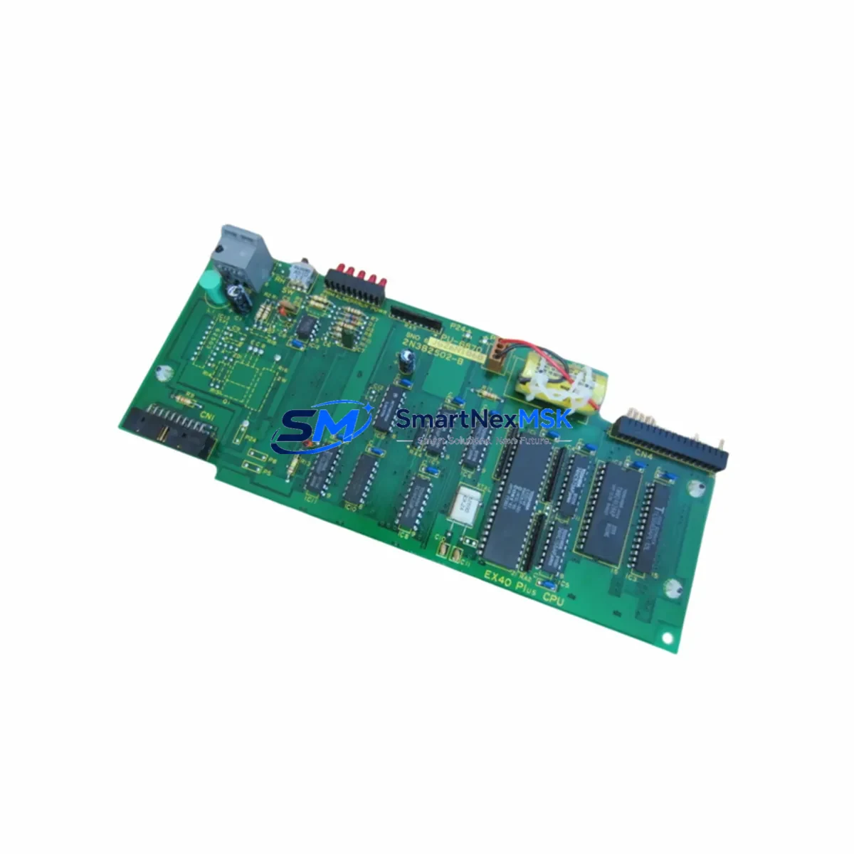
TOSHIBA 2N3B2502-B Retrofit-Ready Sequence Control for T Series: Compatible Modernization & Smooth System Upgrade
The TOSHIBA 2N3B2502-B is a sequence control module engineered for TOSHIBA’s T Series programmable logic controller platform. As legacy T Series installations age and original spare parts become increasingly scarce, the 2N3B2502-B has become an essential retrofit component for engineers tasked with modernizing aging control cabinets, extending production line service life, and maintaining operational continuity without committing to a full system replacement.
Whether you are replacing a failed unit in an active production environment or proactively building retrofit inventory ahead of a planned upgrade cycle, the 2N3B2502-B delivers a wiring-compatible, firmware-consistent solution that minimizes re-engineering effort. All units are sourced from verified supply channels, individually inspected prior to dispatch, and shipped with a 12-month warranty covering functional defects under normal operating conditions.
Upgrade Compatibility Table
| Parameter | Details |
|---|---|
| Compatible Platform | TOSHIBA T Series PLC (T2, T3, T3H variants) |
| Module Function | Sequence Control / Program Execution |
| Backplane Interface | T Series standard bus connector — direct slot replacement, no hardware modification required |
| Communication Compatibility | Compatible with T Series ladder logic and TOSHIBA programming tools; supports RS-485 and Ethernet interface cards in the same rack |
| Installation Requirement | Verify rack slot address and I/O mapping before power-on; confirm CPU module firmware version compatibility |
| Replacement Recommendation | Direct drop-in for failed or end-of-life 2N3B2502-B units; no backplane rewiring required |
| Commissioning Focus | Confirm program upload, I/O scan cycle, HMI tag mapping, and communication link status before returning to automatic operation |
| Warranty | 12 Months — functional defect coverage from shipment date; replacement or refund for verified manufacturing defects |
Retrofit Planning for Existing Automation Systems
Successful integration of the 2N3B2502-B into an existing T Series control system requires a structured pre-installation review. Before removing the failed module, engineers should document the current rack configuration — including the position of the T Series CPU module, any installed T Series Ethernet or RS-485 communication interface cards, and the arrangement of digital input modules and digital output modules occupying adjacent backplane slots.
Power supply capacity is a frequent oversight in retrofit projects. Confirm that the T Series power supply module installed in the rack — typically a 24 VDC or 100–240 VAC unit — can support the combined load of the replacement 2N3B2502-B alongside all existing modules. If the rack is operating near its rated capacity, complete a power budget calculation before proceeding with installation. In multi-rack configurations, also verify that the remote I/O rack connected via the T Series I/O expansion bus is not affected by the module swap.
Terminal wiring on associated I/O modules must be verified against the original wiring diagram. In many aging T Series installations, field wiring has been modified over time without corresponding documentation updates. A physical point-to-point check of all terminal connections on the relevant digital input and output modules is strongly recommended before commissioning the replacement unit. Pay particular attention to any analog input modules or analog output modules sharing the same rack, as signal reference levels can be affected by power sequencing during module replacement.
For systems using TOSHIBA’s proprietary programming software to manage ladder logic on the T Series CPU, confirm that the program version stored in the CPU memory matches the last validated backup. If the 2N3B2502-B is being installed alongside a CPU module replacement or firmware update, re-upload the verified program file and perform a full I/O force test before returning the line to automatic operation. Any HMI panels connected via the T Series communication link — whether a TOSHIBA operator panel or a third-party HMI using a serial or Ethernet driver — should be tested for correct tag resolution and alarm response after the module swap. Programming cables compatible with the T Series platform should be on-site and verified functional before the maintenance window begins.
In multi-rack configurations, verify that the module address assigned to the 2N3B2502-B does not conflict with other modules on the same backplane or connected remote I/O racks. Address conflicts are a common source of startup faults in retrofit projects and can be resolved through the rack configuration utility in the programming software before the first power-on cycle.
Downtime Control During System Migration
Minimizing unplanned downtime is the primary objective in any live-system retrofit. For the 2N3B2502-B replacement, the recommended approach is to complete all pre-installation verification steps — program backup, wiring check, power budget review, and module address confirmation — while the existing module is still in place and the system is in a controlled shutdown state.
Where possible, schedule the physical module swap during a planned maintenance window rather than responding reactively to an in-service failure. Pre-stage the replacement 2N3B2502-B at the site, confirm it has passed outgoing function testing, and have the T Series programming cable and a laptop loaded with the correct software version ready before opening the control cabinet. Ensure that a verified backup of the current CPU program is stored on an external device independent of the control system.
After installation, follow a structured startup sequence: power on the rack, confirm the T Series CPU module enters run mode without fault codes, verify the I/O scan cycle is active across all installed digital and analog modules, check communication link status to any connected HMI or SCADA system, and perform a supervised manual cycle of the controlled process before returning to full automatic operation. This sequence protects the original program logic and ensures field control continuity is maintained throughout the transition. All units shipped from our inventory undergo pre-shipment functional testing — each 2N3B2502-B is verified for correct bus communication, module identification, and basic I/O response before dispatch, reducing the risk of receiving a non-functional unit during a time-critical retrofit.
Retrofit Support FAQ
Q: Is the 2N3B2502-B a direct replacement for the original TOSHIBA T Series module?
A: Yes. The 2N3B2502-B is designed as a slot-compatible replacement for the original unit in T Series racks. No hardware modification to the backplane or rack is required. Confirm the module address setting matches your existing configuration before power-on.
Q: What commissioning steps are required after installation?
A: After physical installation, upload the verified program to the CPU if required, confirm I/O mapping is intact across all digital and analog I/O modules, check communication link status to connected HMI or SCADA systems, and perform a supervised manual cycle of the process. A full I/O force test is recommended before returning to automatic operation.
Q: How do I verify wiring compatibility before replacing the module?
A: Cross-reference the original wiring diagram against the current terminal connections on all associated I/O modules. Pay particular attention to any field wiring changes made since the original installation. A point-to-point continuity check is the most reliable method for aging T Series installations where documentation may be incomplete or outdated.
Q: What does the 12-month warranty cover?
A: The warranty covers functional defects in the module under normal operating conditions for 12 months from the shipment date. Units that fail due to manufacturing defects or component failure within this period will be replaced or refunded. The warranty does not cover damage resulting from incorrect installation, overvoltage, or physical mishandling.
© 2026 SMARTNEXMSK. All rights reserved.
Original Source: https://smartnexmsk.com
Contact: sales@smartnexmsk.com | +86 18259474341