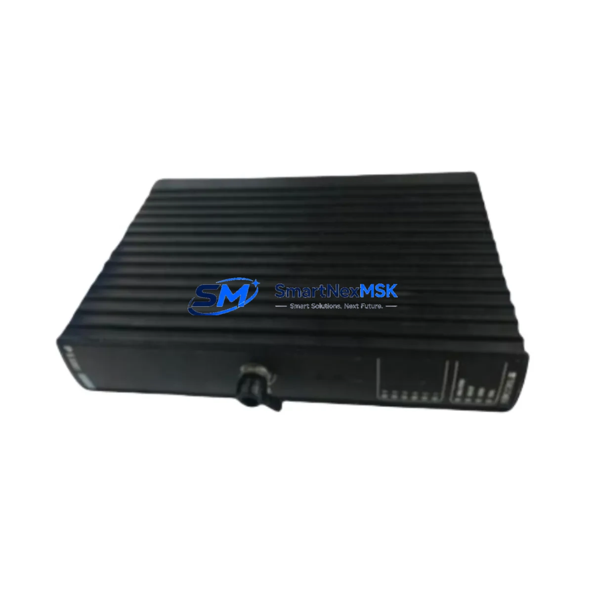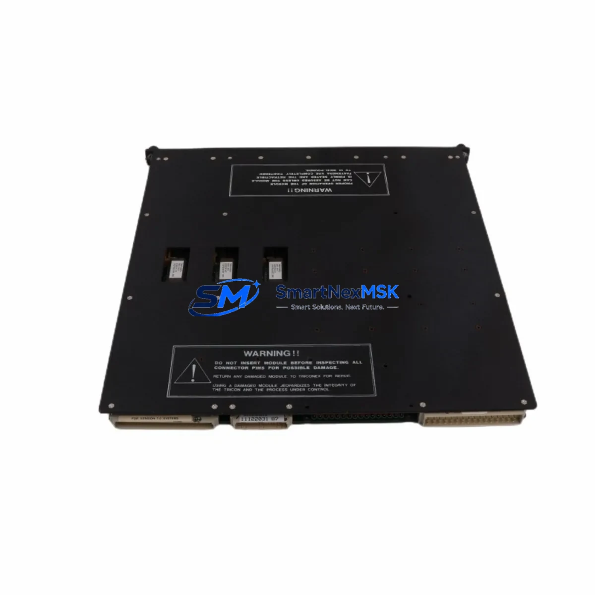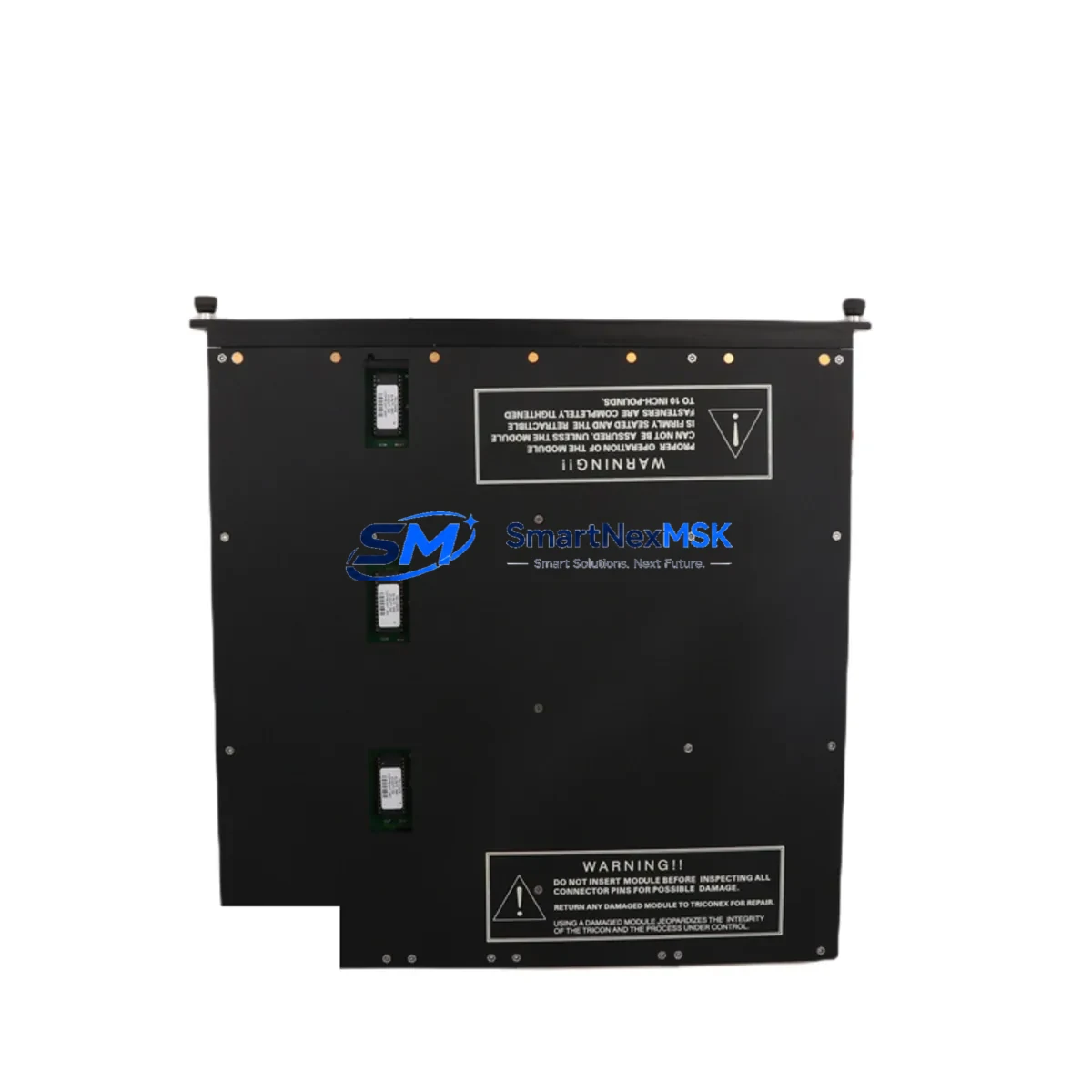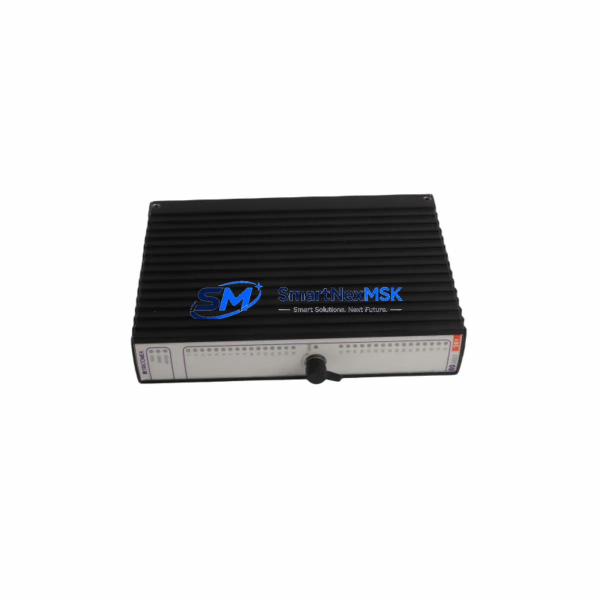
TRICONEX 3511 Retrofit-Ready Pulse Input Module for Tricon TMR Control Systems
The TRICONEX 3511 is a Pulse Input Module designed for the Tricon Triple Modular Redundant (TMR) Safety Instrumented System (SIS) platform. As legacy Tricon systems approach end-of-support milestones, the 3511 remains one of the most sought-after retrofit and replacement components for engineers managing aging safety-critical control architectures in oil & gas, petrochemical, power generation, and chemical processing facilities. Whether you are replacing a failed module, upgrading a control cabinet, or executing a phased system modernization, the TRICONEX 3511 provides a verified drop-in solution that preserves your existing wiring, backplane connections, and TriStation 1131 program logic without requiring a full platform migration.
Our inventory is sourced from authorized distribution channels and subject to full functional testing prior to shipment. Each unit is covered by a 12-month warranty and ships with documentation supporting your site acceptance test (SAT) and commissioning records.
Upgrade Compatibility Table
| Parameter | Details |
|---|---|
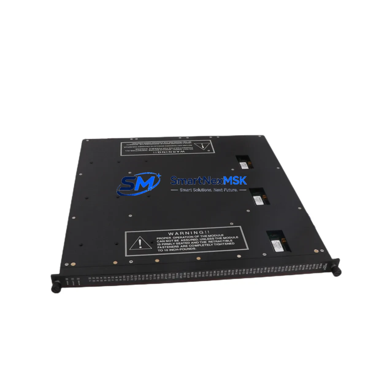
| Module Model | TRICONEX 3511 |
| Module Type | Pulse Input Module |
| Platform Compatibility | Tricon TMR (Triple Modular Redundant) SIS |
| Backplane Interface | Tricon standard backplane bus; compatible with Tricon chassis / rack |
| Installation Requirement | Hot-swap capable in powered Tricon chassis; no rack modification required |
| Communication Compatibility | TriBus internal communication; compatible with Tricon Main Processor (e.g., 3008, 3006) and TriStation 1131 programming environment |
| Wiring Compatibility | Terminal block wiring retained from legacy 3511 installations; no rewiring required for direct replacement |
| Replacement Recommendation | Direct replacement for failed or end-of-life TRICONEX 3511 units; suitable for like-for-like swap |
| Commissioning Notes | Verify module address assignment in TriStation 1131; confirm pulse input channel configuration and scaling parameters post-installation |
| Warranty | 12-Month Warranty — functional test report available upon request |
Retrofit Planning for Existing Automation Systems
Successful integration of the TRICONEX 3511 into an existing Tricon TMR system requires a structured retrofit plan that accounts for the full control architecture. Before initiating a module swap, engineers should audit the Tricon chassis configuration to confirm available slot positions and verify that the Tricon Main Processor — typically a 3008 or 3006 — is running a firmware version compatible with the 3511’s pulse input channel definitions. The chassis backplane must be inspected for physical integrity, and any Tricon Termination Assemblies (TCMs) connected to the 3511’s field wiring should be documented for terminal mapping.
In systems where the 3511 interfaces with rotating equipment — turbines, compressors, or pump trains — the pulse input scaling and engineering unit conversion configured in TriStation 1131 must be preserved exactly. Backup the current TriStation project file before any hardware change. If the system includes a Tricon Communication Module (TCM 4351 or TCM 4352) for Modbus or HART integration, confirm that the communication link remains unaffected during the module replacement window.
For control cabinets that also house a Tricon Power Module (e.g., 8310 or 8311), verify that the total power budget accommodates the 3511 without exceeding chassis load limits. In multi-chassis configurations connected via the Tricon Enhanced Intelligent Bus (EICB), module address conflicts must be resolved in the TriStation I/O map before the replacement unit is brought online. Where the system includes a Tricon Analog Input Module (3703E or 3805E) on the same chassis, confirm that the shared backplane communication does not introduce scan-cycle latency that could affect SIS response time calculations.
If the retrofit scope extends to HMI integration — particularly where a Wonderware, iFIX, or third-party SCADA system reads Tricon data via OPC or Modbus TCP — the HMI tag database should be validated against the replacement module’s channel assignments to prevent display errors or alarm suppression during the transition. For sites using a Tricon Safety Manager (TSM) or Triconex Safety System Gateway (SSG), the gateway configuration should be reviewed to ensure the 3511’s pulse data is correctly mapped to the process historian or DCS interface.
Downtime Control During System Migration
Minimizing unplanned downtime during a TRICONEX 3511 replacement is achievable through disciplined pre-work and a clearly defined change management procedure. The recommended approach is to schedule the module swap during a planned maintenance window, with the Tricon system operating in its normal TMR voting configuration up to the point of physical replacement. Because the Tricon TMR architecture provides 2-out-of-3 (2oo3) voting logic, a single module can be removed and replaced while the remaining two legs maintain safety function — provided the system is not already in a degraded state.
Prior to the swap, the TriStation 1131 diagnostic display should be used to confirm that all three legs of the affected I/O point are healthy. The replacement 3511 should be pre-configured and bench-tested where possible, with channel addresses and pulse input parameters verified against the project documentation. After installation, the TriStation diagnostic should confirm that the new module has joined the TMR voting group and that all three legs are reporting consistent values before the maintenance window is closed.
Original program logic does not need to be modified for a like-for-like 3511 replacement. The TriStation 1131 project file remains unchanged, and no download to the controller is required if the module address and channel configuration are identical to the unit being replaced. Field calibration of connected sensors — flow transmitters, speed sensors, or proximity switches — should be verified post-replacement to confirm that pulse input scaling matches the process baseline. Maintaining a spare 3511 in local inventory is strongly recommended for sites where the Tricon system protects a critical process unit with a high cost of unplanned shutdown.
Retrofit Support FAQ
Q1: Is the TRICONEX 3511 a direct drop-in replacement for an existing 3511 in my Tricon chassis?
Yes. The 3511 is a like-for-like replacement. The module slots into the same backplane position, uses the same terminal wiring, and requires no changes to the TriStation 1131 project file, provided the replacement unit carries the same hardware revision or a compatible successor revision. Confirm the hardware revision label on the original unit before ordering if your site has strict change management requirements.
Q2: What commissioning steps are required after installing the replacement 3511?
After physical installation, open TriStation 1131 and navigate to the diagnostic display for the affected chassis. Confirm that the new 3511 is recognized in all three TMR legs and that the module status indicators show normal operation. Verify pulse input channel scaling and engineering unit parameters against the project baseline. If the system includes a Tricon Communication Module for external data exchange, confirm that the pulse data is correctly appearing in the Modbus or OPC data map. Document the replacement in your site’s management of change (MOC) record.
Q3: Can the 3511 be used in a Tricon system that also includes older modules such as the 3501 or 3664?
Yes. The Tricon TMR platform supports mixed I/O module configurations within the same chassis. The 3511 coexists with other Tricon I/O modules — including the 3501 Digital Input Module, the 3664 Analog Output Module, and the 3703E Analog Input Module — without compatibility issues, provided the chassis backplane and Main Processor firmware support the installed module set. Review the Tricon System Planning Guide for your specific firmware version to confirm the supported module matrix.
Q4: What does the 12-month warranty cover, and is a functional test report available?
The 12-month warranty covers functional defects identified under normal operating conditions consistent with the module’s rated specifications. Each unit undergoes pre-shipment functional testing. A functional test report is available upon request and can be provided with the shipment to support your incoming inspection and SAT documentation. Warranty claims are processed through our sales team at sales@smartnexmsk.com.
© 2026 SMARTNEXMSK. All rights reserved.
Original Source: https://smartnexmsk.com
Contact: sales@smartnexmsk.com | +86 18259474341