Triconex 3700A Maintenance-Ready Spare for Tricon Automation
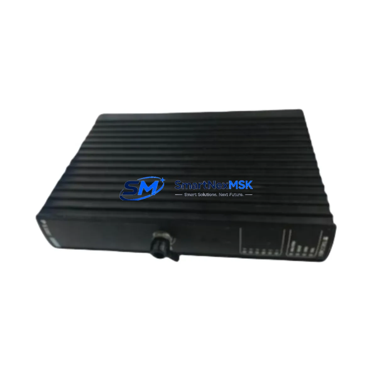
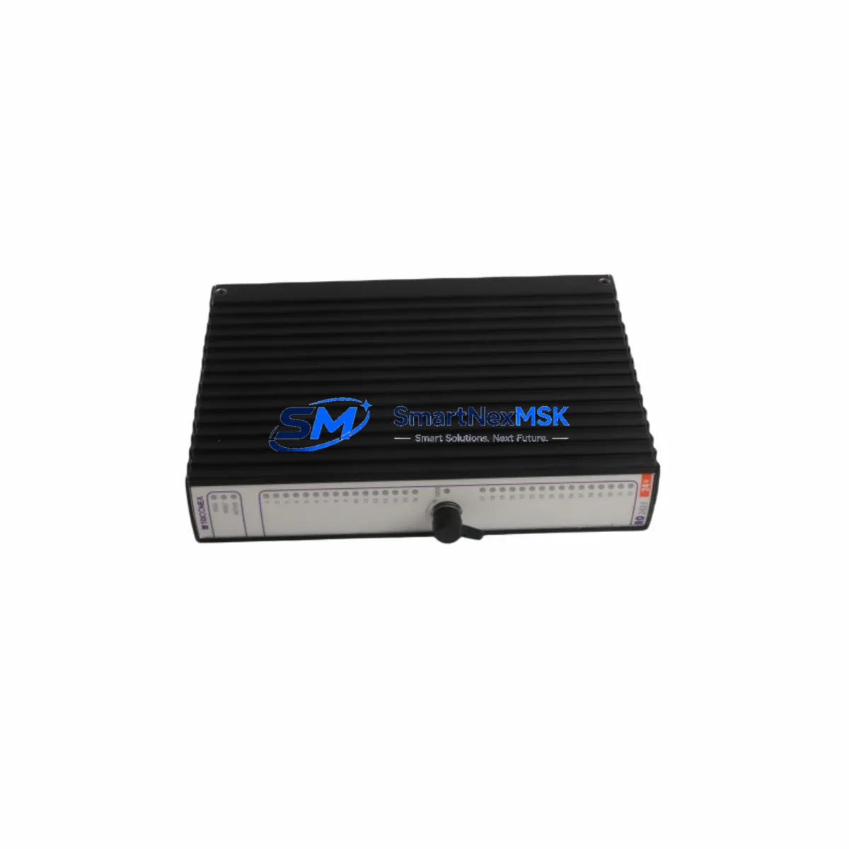
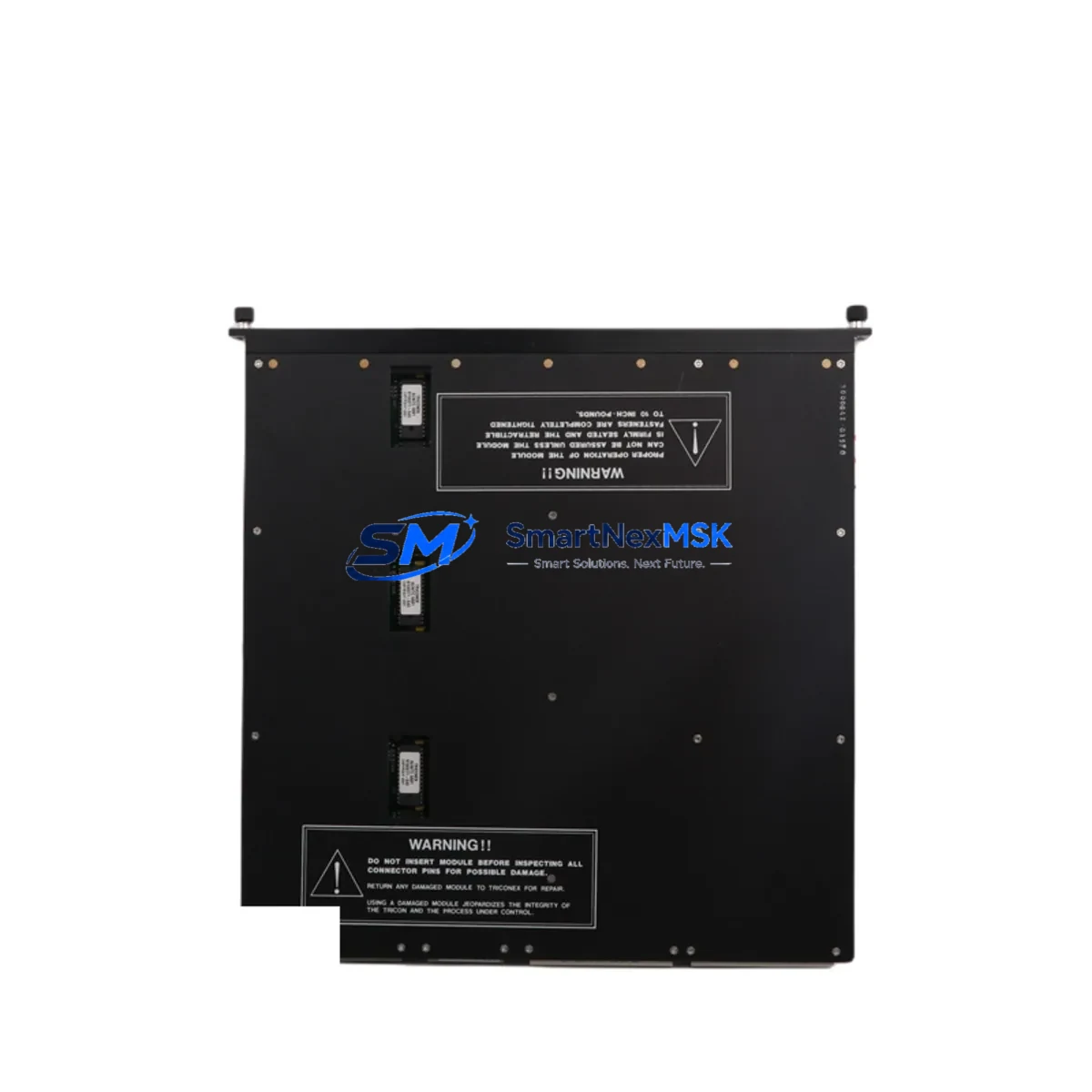
The Triconex 3700A is an original Analog Input Module designed for the Tricon Triple Modular Redundant (TMR) Safety System, certified to SIL 3 under IEC 61511 and IEC 61508. As a critical component in Safety Instrumented Systems (SIS) across oil & gas, petrochemical, power generation, and chemical processing industries, the 3700A plays a central role in continuous process monitoring and emergency shutdown (ESD) logic. Maintaining a verified spare of this module is not optional — it is a fundamental requirement of any credible maintenance strategy for Tricon-based control architectures.
For maintenance engineers and procurement teams managing aging Tricon systems, sourcing a tested, original 3700A with documented compatibility is the fastest path to restoring full TMR redundancy after a module fault. This unit ships tested, with full functional verification, and is backed by a 12-month warranty.
Spare Maintenance Table
| Parameter | Specification |
|---|---|
| Part Number / SKU | 3700A |
| Brand | Triconex (Schneider Electric) |
| Module Type | Analog Input Module |
| System Compatibility | Tricon TMR Safety System (v9.x / v10.x chassis) |
| Safety Integrity Level | SIL 3 (IEC 61511 / IEC 61508) |
| Input Channels | 16 channels (4–20 mA / 1–5 V configurable) |
| Input Range | 4–20 mA current loop; 1–5 VDC voltage |
| Resolution | 12-bit A/D conversion |
| Isolation | Channel-to-channel and channel-to-backplane optical isolation |
| Operating Temperature | 0°C to 60°C (32°F to 140°F) |
| Power Consumption | Supplied via Tricon backplane (chassis-powered) |
| Mounting | Tricon chassis backplane slot (hot-swap capable) |
| Certifications | SIL 3, CE, FM, CSA |
| Application Environment | Oil & Gas ESD, Burner Management, Chemical SIS, Power Plant Safety |
| Maintenance Recommendation | Inspect annually; replace on first diagnostic fault indication |
| Warranty | 12 Months — tested and verified before shipment |
Maintenance Planning for Continuous Operation
When a Triconex 3700A module triggers a diagnostic fault or fails a self-test during routine inspection, the replacement workflow must be executed with precision to preserve TMR voting integrity. Maintenance engineers should treat the 3700A replacement as a system-level event, not an isolated module swap. Before and after installing the spare, the following associated components must be inspected and verified:
- Tricon Power Module (e.g., 8312 or 8310) — Verify chassis power supply output is within spec; a degraded power module can cause false analog input faults and corrupt 3700A diagnostics.
- Tricon Main Chassis / Backplane — Inspect backplane connector pins for oxidation or mechanical damage before seating the replacement 3700A.
- Field Termination Assembly (FTA) / Terminal Board — The FTA connected to the 3700A carries all 4–20 mA field wiring. Inspect for loose terminals, moisture ingress, and correct shielding continuity.
- Triconex 3703E or 3721 Analog Input Modules — If the 3700A is part of a mixed analog input configuration, verify adjacent modules are not showing latent faults that could indicate a shared field wiring or power issue.
- Signal Isolators / Barriers (e.g., Zener barriers or galvanic isolators) — For intrinsically safe loops, confirm that signal isolators between the field transmitter and the 3700A input are within calibration and not contributing to signal drift.
- 4–20 mA Field Transmitters — Loop-test each transmitter connected to the replaced module to confirm signal integrity before returning the system to automatic mode.
- Tricon Communication Module (e.g., 4351B or 4119A) — After module replacement, verify that the Tricon communication module is correctly reporting the new module status to the DCS or SCADA host.
- Triconex TriStation 1131 Engineering Workstation — Use TriStation to perform a post-replacement module diagnostic scan, confirm the 3700A is recognized in the correct slot, and validate I/O configuration mapping.
- Fuses and Overcurrent Protection on Field Loops — Check loop fuses on the FTA or marshalling cabinet; a blown fuse on a 4–20 mA loop can mimic a module fault and should be ruled out before condemning the 3700A.
- Tricon Digital Output Modules (e.g., 3664 or 3625) — In ESD applications, confirm that digital output modules driving final elements (valves, relays) are responding correctly after the analog input restoration, as SIS logic may have latched during the fault period.
Stocking a minimum of one verified 3700A spare per Tricon chassis is the industry-standard recommendation for SIS maintenance programs operating under IEC 61511 functional safety management requirements. For facilities with multiple Tricon systems, a centralized spare parts inventory with documented proof-test records for each spare module significantly reduces mean time to repair (MTTR) during unplanned shutdowns.
Site Replacement Workflow
The Triconex 3700A supports hot-swap replacement within the Tricon chassis, allowing maintenance teams to replace a faulted module without a full system shutdown — a critical advantage in continuous-process environments where planned downtime windows are measured in hours per year.
Step 1 — Fault Confirmation: Use TriStation 1131 or the Tricon panel LEDs to confirm the 3700A module fault is hardware-based (not a configuration or field wiring issue). Document the fault code and affected channels.
Step 2 — Spare Verification: Before removing the faulted module, confirm the replacement 3700A has the same firmware revision and hardware revision as the installed unit. Revision mismatches can cause compatibility issues in older Tricon v9.x systems.
Step 3 — Hot-Swap Execution: With the Tricon system in TMR mode and the remaining two legs maintaining voting, carefully extract the faulted 3700A from its chassis slot. Insert the replacement module and allow the Tricon system to perform its automatic self-test and synchronization sequence (typically 30–90 seconds).
Step 4 — Post-Replacement Validation: Confirm all 16 analog input channels are reading correctly in TriStation. Perform a loop check on critical channels. Verify the module status LED shows green and no diagnostic faults are active.
Step 5 — Documentation: Update the site maintenance log with the replacement date, module serial number, firmware revision, and post-replacement test results. Retain the faulted module for failure analysis or return-to-vendor evaluation.
For legacy Tricon systems where the 3700A has been discontinued by the OEM, sourcing a tested original spare from a qualified industrial parts supplier is the most cost-effective strategy for extending system life without a full platform migration. This approach preserves existing SIS validation documentation and avoids the significant engineering cost of requalifying a replacement platform under IEC 61511.
Spare Parts Support FAQ
Q1: Is this Triconex 3700A an original module or a refurbished unit?
This is an original Triconex 3700A module. Each unit undergoes functional testing prior to shipment, including analog input channel verification, backplane communication check, and self-diagnostic validation. A 12-month warranty is provided from the date of shipment, covering hardware defects and functional failures under normal operating conditions.
Q2: How do I confirm compatibility with my existing Tricon system version?
The 3700A is compatible with Tricon TMR chassis systems running firmware v9.x and v10.x. To confirm compatibility, provide your Tricon chassis model number and current firmware version. Hardware revision compatibility can be verified against the Triconex module compatibility matrix. Our technical team can assist with revision matching before shipment to eliminate on-site compatibility risk.
Q3: What is the recommended spare parts stocking strategy for the 3700A?
For facilities operating a single Tricon chassis with 3700A modules installed, a minimum of one spare module is recommended. For multi-chassis installations or facilities with extended lead times for emergency procurement, two to three spares per site is the standard recommendation under IEC 61511 functional safety management guidelines. Spares should be stored in anti-static packaging in a climate-controlled environment and proof-tested annually.
Q4: What is the lead time and shipping process for this module?
In-stock units ship within 1–3 business days. Each module is tested, packaged in anti-static ESD-safe materials, and shipped with a functional test report. Express shipping options are available for emergency maintenance situations. All shipments include tracking and are insured for the full declared value. Contact our team for urgent requirements and we will prioritize dispatch accordingly.
© 2026 SMARTNEXMSK. All rights reserved.
Original Source: https://smartnexmsk.com
Contact: sales@smartnexmsk.com | +86 18259474341