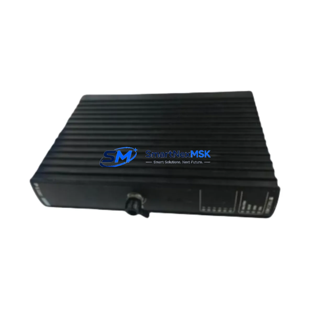
Triconex 4351B Maintenance-Ready Spare for Tricon TMR Automation
The Triconex 4351B is a critical communication module within the Tricon Triple Modular Redundant (TMR) Safety Instrumented System (SIS) architecture. Designed for high-availability process control environments — including oil & gas, petrochemical, power generation, and chemical processing — this module serves as the backbone of inter-chassis and host communication in safety-critical control loops. Sourcing a verified, original-specification 4351B spare is essential for any maintenance team responsible for minimizing unplanned downtime and sustaining SIS integrity.
At SMARTNEXMSK, every Triconex 4351B unit is sourced from authorized supply channels, subjected to pre-shipment functional verification, and dispatched with a 12-month warranty. Whether you are replenishing your critical spare inventory, executing a planned turnaround, or responding to an emergency fault isolation event, the 4351B is available for immediate dispatch.
Spare Maintenance Table
| Parameter | Specification / Detail |
|---|---|
| Part Number / SKU | 4351B |
| Brand | Triconex (Schneider Electric) |
| Series | Tricon TMR (Triple Modular Redundant) |
| Module Type | Safety Communication Module |
| System Compatibility | Tricon TMR Safety PLC (Tricon v9/v10 chassis) |
| Communication Interface | Tricon Communication Module (TCM) bus; host interface |
| Operating Voltage | Supplied via Tricon backplane (internal bus power) |
| Operating Temperature | 0°C to 60°C (32°F to 140°F) |
| Mounting | Tricon main chassis slot (hot-swap capable per SIS procedure) |
| Certification | IEC 61508 SIL 3 rated system component |
| Country of Origin | United States |
| Weight | Approx. 2.9 kg (packaged) |
| Condition | Original, new or refurbished-to-spec; tested before shipment |
| Warranty | 12 Months — covers functional defects under normal operating conditions |
| Lead Time | In-stock: ships within 2 business days; ex-stock subject to availability |
| Application Sectors | Oil & Gas, Petrochemical, Power Generation, Chemical Processing, Offshore Platforms |
Maintenance Planning for Continuous Operation
When a Triconex 4351B communication module is flagged during a routine control cabinet inspection or fault diagnostic cycle, experienced maintenance engineers know that the replacement event is an opportunity to audit the broader SIS cabinet health. The 4351B does not operate in isolation — it interfaces with the Tricon main chassis backplane, the Tricon Power Module (e.g., 8310 or 8312 series), and the host communication network. A thorough replacement workflow should therefore include a parallel inspection of the following components:
- Tricon Power Modules (8310 / 8312): Verify DC bus voltage stability and redundant power feed integrity before and after module swap. A marginal power module can cause intermittent communication faults that mimic a failed 4351B.
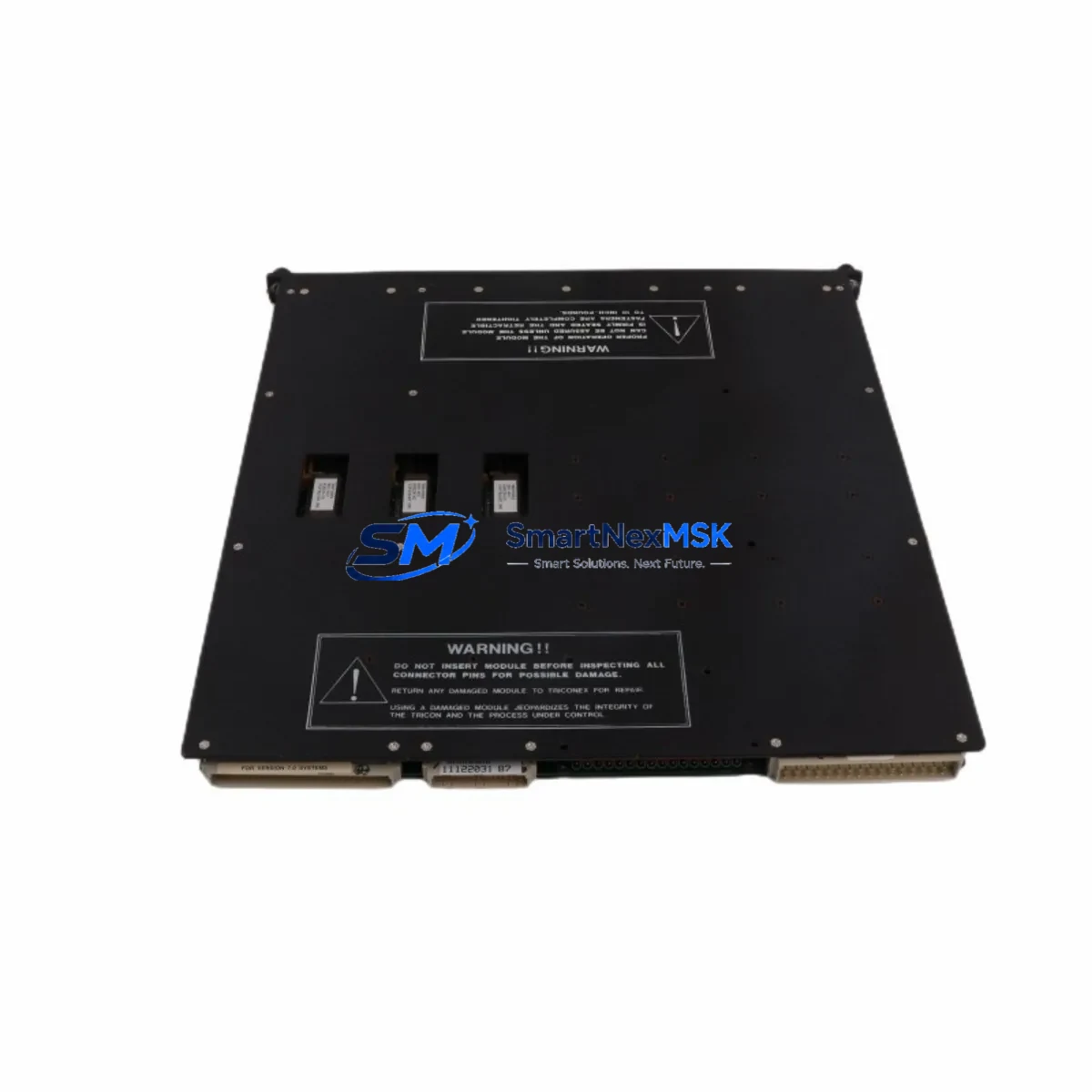
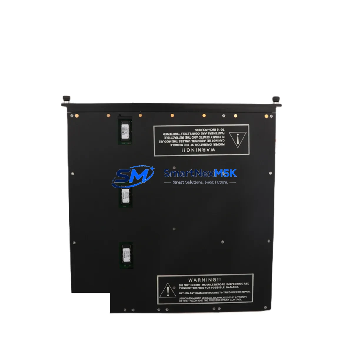
- Tricon Main Chassis Backplane: Inspect connector pins and slot contacts for oxidation or mechanical wear. A degraded backplane slot can cause recurring communication module failures.
- Tricon Digital Input Modules (e.g., 3501E, 3503E): During planned maintenance windows, validate DI module status and wiring continuity on safety-critical input loops associated with the communication network.
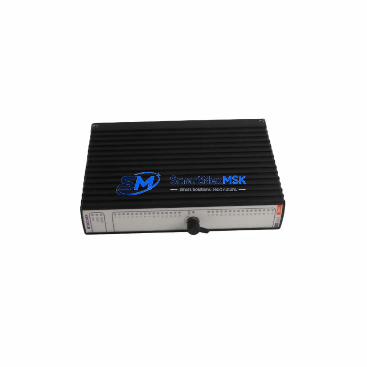
- Tricon Digital Output Modules (e.g., 3601E, 3603E): Confirm DO module health and relay output integrity, particularly for ESD and fire-and-gas output loops that depend on reliable SIS communication.
- Tricon Analog Input Modules (e.g., 3700A, 3703E): Check AI module calibration records and signal wiring for process-critical measurement loops that feed into the safety logic solved by the Tricon controller.
- Tricon Communication Interface Cables: Inspect TCM bus cables and host interface cables for insulation damage, connector seating, and bend-radius compliance. Cable degradation is a common root cause of intermittent communication faults.
- Tricon Main Processor Module (e.g., 4351, 4352 series): Cross-reference firmware revision compatibility between the replacement 4351B and the installed main processor to ensure seamless re-integration without configuration mismatch.
- Terminal Blocks and Field Wiring Terminations: Verify torque on all terminal block connections within the SIS cabinet. Loose terminations can introduce ground loops or signal noise that stress communication module diagnostics.
- Surge Protection and Fusing: Confirm that field-side surge suppressors and fuse ratings on I/O circuits remain within specification. Overstressed protection devices are often overlooked during communication module fault investigations.
- Triconex TriStation Engineering Workstation Connection: After module replacement, re-establish TriStation connectivity and perform a full system status check to confirm TMR voting logic, module health LEDs, and diagnostic registers are all clear before returning the SIS to service.
Maintaining a structured spare parts kit that includes the 4351B alongside the above components significantly reduces mean time to repair (MTTR) and supports a proactive maintenance culture aligned with IEC 61511 functional safety management requirements.
Site Replacement Workflow
Replacing a Triconex 4351B in a live Tricon TMR system requires adherence to the site-specific Management of Change (MOC) procedure and the Triconex hot-swap guidelines. The following workflow is recommended for maintenance engineers executing an in-service replacement:
- Pre-Replacement Verification: Confirm the replacement 4351B part number, firmware label, and hardware revision match the installed unit. Cross-reference the Tricon system configuration file in TriStation to validate slot assignment and communication parameters.
- System Status Check: Using TriStation or the Tricon panel display, verify that the remaining two TMR legs are healthy and that the system is in a safe state to tolerate a single-module removal without triggering a spurious trip.
- Module Extraction: Following Triconex ESD precautions, extract the faulty 4351B from its chassis slot. Document the slot number and any fault codes displayed prior to removal.
- Module Installation: Insert the replacement 4351B firmly into the chassis slot. The Tricon TMR architecture supports online module replacement — the system will automatically synchronize the new module with the active TMR voting logic within the configured re-integration timeout.
- Post-Replacement Validation: Monitor TriStation diagnostics for a minimum of 15 minutes post-insertion to confirm all three TMR legs are voting correctly, communication registers are synchronized, and no new fault codes are generated.
- Documentation: Update the site maintenance log, spare parts inventory record, and the SIS safety case documentation to reflect the completed replacement event.
This workflow minimizes process disruption, maintains SIS availability, and ensures full traceability for functional safety audit purposes. SMARTNEXMSK ships the 4351B with a test report and part identification label to support your site documentation requirements.
Spare Parts Support FAQ
Q1: Is the Triconex 4351B still available as a new original spare, or is it an end-of-life component?
The 4351B is a mature Triconex product. While Schneider Electric may have transitioned some Tricon series components to limited availability, SMARTNEXMSK maintains stock of original and refurbished-to-specification 4351B units to support legacy Tricon TMR systems. All units are functionally tested prior to shipment. Contact sales@smartnexmsk.com to confirm current stock status and lead time.
Q2: How do I verify compatibility between the replacement 4351B and my installed Tricon system version?
Compatibility is determined by the Tricon chassis generation (v9 or v10), the main processor firmware revision, and the TriStation project configuration. Provide your system serial number, chassis model, and current firmware version when placing your order, and our technical team will confirm hardware revision compatibility before dispatch.
Q3: What pre-shipment testing does SMARTNEXMSK perform on the Triconex 4351B?
Each 4351B unit undergoes a functional bench test that verifies communication interface integrity, backplane connector condition, and module self-diagnostic pass status. Units that do not pass all test criteria are not dispatched. A test record is included with each shipment to support your incoming inspection and site acceptance procedures.
Q4: What does the 12-month warranty cover, and what is the return process if a fault is identified after installation?
The 12-month warranty covers functional defects arising under normal operating conditions consistent with Triconex installation specifications. Physical damage caused by incorrect installation, overvoltage events, or environmental exposure outside rated limits is excluded. To initiate a warranty claim, contact sales@smartnexmsk.com with your order reference, installation date, and a description of the fault symptom. SMARTNEXMSK will arrange return logistics and provide a replacement or repair within an agreed lead time.
© 2026 SMARTNEXMSK. All rights reserved.
Original Source: https://smartnexmsk.com
Contact: sales@smartnexmsk.com | +86 18259474341