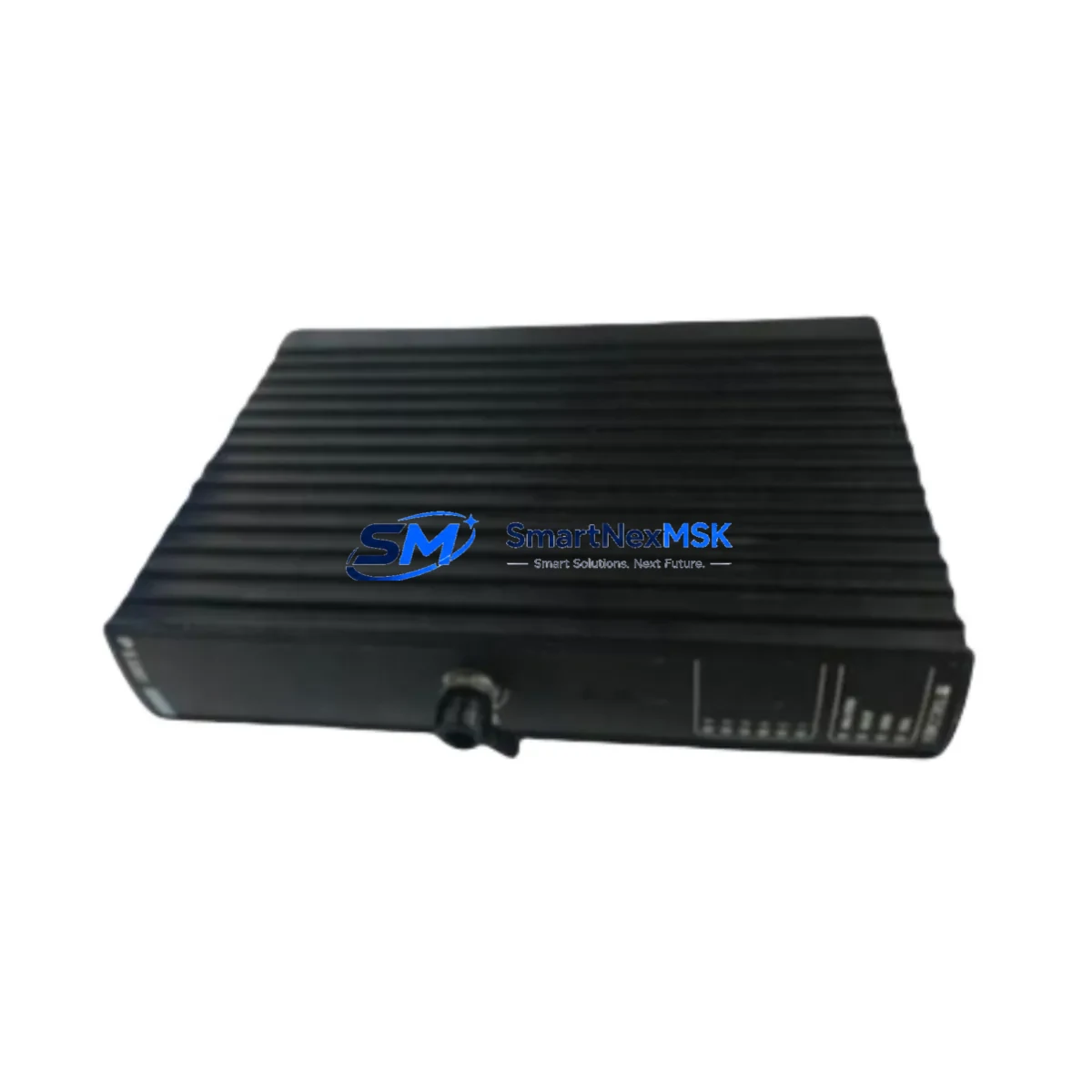
TRICONEX 7400208C-020 Retrofit-Ready DI Terminator for Tricon TMR Control Systems
The TRICONEX 7400208C-020 is a Digital Input (DI) External Terminator Assembly designed for use within the Tricon Triple Modular Redundancy (TMR) safety system platform — one of the most widely deployed Safety Instrumented System (SIS) architectures in the oil & gas, petrochemical, power generation, and chemical processing industries. As legacy Tricon installations approach end-of-life or require partial modernization, the 7400208C-020 serves as a critical retrofit component enabling engineers to restore full I/O functionality, extend system service life, and defer costly full-system replacements.
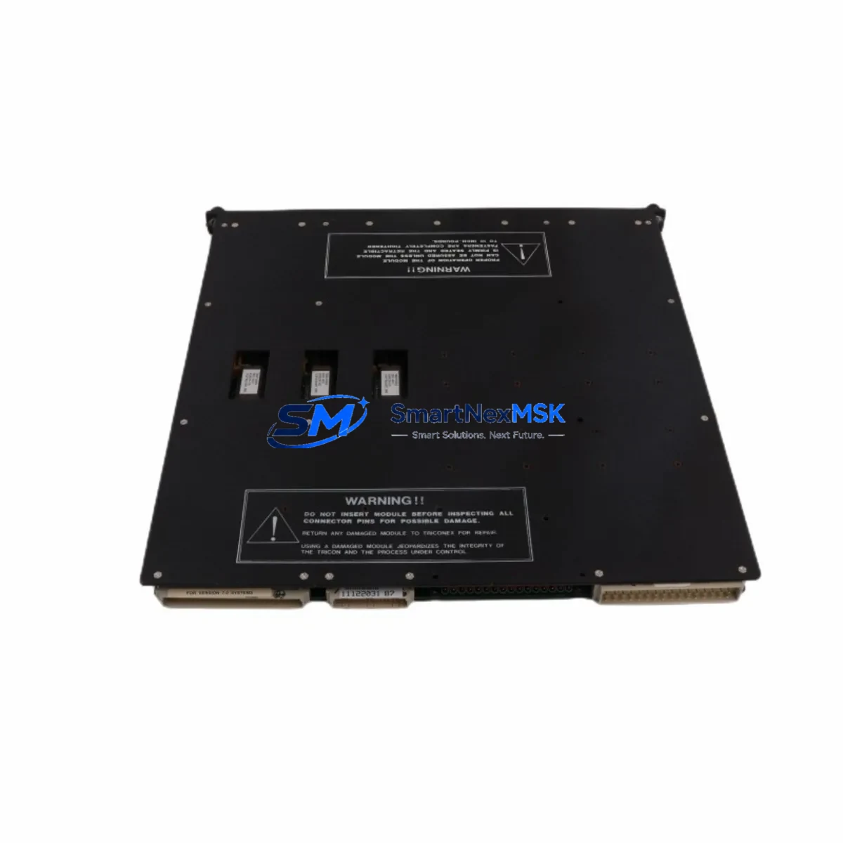
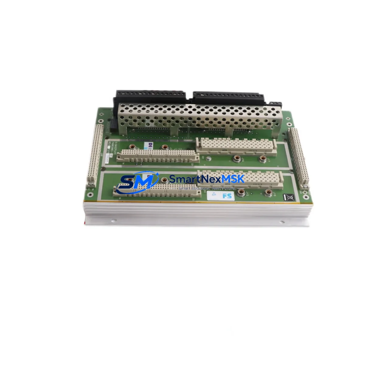
This terminator panel interfaces directly with the Tricon DI module — typically the TRICONEX 3501 or 3503 Digital Input module — providing the field-side terminal block connections required for discrete sensor wiring. In retrofit scenarios, the 7400208C-020 is frequently used to replace degraded or discontinued termination assemblies without disturbing the existing backplane, chassis, or controller logic. Its pin-compatible design ensures that field wiring, cable harnesses, and marshalling connections remain intact during the swap, significantly reducing downtime and re-commissioning effort.
Upgrade Compatibility Table
| Parameter | Details |
|---|---|
| Part Number | 7400208C-020 |
| Brand / OEM | TRICONEX (Invensys / Schneider Electric) |
| Compatible Platform | Tricon TMR Safety System |
| Compatible DI Modules | TRICONEX 3501, 3503, 3504 |
| Module Type | DI External Terminator Assembly |
| Installation Interface | Tricon chassis backplane slot (standard Tricon termination bay) |
| Communication Compatibility | Tricon TriBus internal communication; compatible with TriStation 1131 programming environment |
| Replacement Suitability | Direct drop-in replacement for degraded or discontinued 7400208C-020 units |
| Commissioning Notes | Verify module address assignment in TriStation 1131; confirm I/O channel mapping before energizing |
| Warranty | 12 Months — covers manufacturing defects and functional failure under normal operating conditions |
| Origin | CN |
| Shipping | Global express shipping; ESD-safe packaging; pre-shipment functional test available on request |
Retrofit Planning for Existing Automation Systems
Successful integration of the TRICONEX 7400208C-020 into an existing Tricon TMR installation requires careful pre-retrofit planning across several engineering disciplines. Before initiating any hardware swap, the site engineer should audit the current Tricon chassis and backplane configuration — specifically confirming available slot positions, power budget headroom from the TRICONEX 8310 or 8312 Power Supply module, and the physical condition of the termination bay connectors.
Field wiring connected to the terminator must be documented and labeled prior to removal. In many aging installations, the original as-built drawings may not reflect field modifications made over years of operation. A physical point-to-point verification of each DI channel against the TriStation 1131 I/O configuration is strongly recommended. Engineers should also confirm that the TRICONEX 3706A or 3721 Main Processor module firmware version is compatible with the terminator revision being installed, as certain firmware releases introduced changes to DI channel diagnostics and fault reporting behavior.
Where the retrofit involves expanding I/O capacity — for example, adding new field instruments to an existing safety loop — the 7400208C-020 may be deployed alongside additional TRICONEX 3501 DI modules and corresponding TRICONEX 3700A or 3700E communication modules to extend the Tricon node’s reach. In multi-chassis configurations, the TRICONEX 4351B or 4352B Hiway Cable interconnects must be verified for signal integrity before commissioning the expanded I/O segment.
For installations migrating from older Tricon v9 or v10 hardware to current-generation Tricon CX or Tricon v11 platforms, the 7400208C-020 terminator remains compatible with the legacy termination bay standard, allowing the field wiring infrastructure to be preserved while the controller and I/O modules are upgraded. This hybrid approach — retaining proven field termination hardware while modernizing the processing and communication layers — is a widely adopted strategy for minimizing capital expenditure and reducing the scope of safety validation re-testing required under IEC 61511.
HMI integration should also be reviewed during retrofit planning. If the site operates a Wonderware InTouch, Aveva System Platform, or Yokogawa FAST/TOOLS SCADA system connected to the Tricon via Modbus TCP, OPC DA, or TriStation protocol, the engineer must confirm that any I/O address changes introduced by the retrofit are reflected in the HMI tag database before returning the system to automatic control.
Downtime Control During System Migration
Minimizing unplanned downtime is the primary operational constraint in any Tricon TMR retrofit project. The TMR architecture itself provides a significant advantage: because the system operates with three independent processing legs (Leg A, Leg B, Leg C), it is possible in many configurations to perform maintenance on one leg while the remaining two legs maintain the safety function — subject to site-specific safety procedures and the approval of the functional safety engineer.
Before removing the 7400208C-020 terminator, the engineer should place the affected DI channels into a bypass or inhibit state within TriStation 1131, ensuring that the safety logic does not interpret the temporary loss of field signal as a process fault. The original program logic — including cause-and-effect matrices, interlock sequences, and diagnostic routines — must be preserved without modification. A full backup of the Tricon application program should be taken and stored offline before any hardware change is initiated.
Upon installation of the replacement 7400208C-020, the engineer should perform a channel-by-channel continuity check at the terminator before re-energizing the field instruments. Each DI channel should be exercised through its full operating range — open circuit, closed circuit, and fault states — to verify correct signal propagation through the new terminator to the DI module and into the TriStation diagnostic display. Only after all channels have been verified should the bypass or inhibit state be removed and the safety function returned to automatic operation.
All retrofit activities should be documented in the site’s Management of Change (MOC) system, with pre- and post-retrofit functional test records retained as part of the safety case documentation. Our team provides pre-shipment functional testing of the 7400208C-020 upon request, with test reports available to support your site MOC package. Every unit ships with a 12-month warranty covering manufacturing defects and functional failure under normal operating conditions.
Retrofit Support FAQ
Q1: Is the TRICONEX 7400208C-020 a direct replacement for the original part, or are there wiring or configuration changes required?
The 7400208C-020 is designed as a pin-compatible replacement for the original Tricon DI External Terminator. In most installations, field wiring can be reconnected to the new terminator without modification. However, engineers should verify the DI channel address assignments in TriStation 1131 and confirm that the module slot position in the Tricon chassis matches the original configuration. No firmware changes are typically required for a like-for-like replacement.
Q2: Can this terminator be used with both Tricon v9/v10 and current-generation Tricon CX hardware?
Yes. The 7400208C-020 terminator is compatible with the standard Tricon termination bay interface used across Tricon v9, v10, v11, and Tricon CX platforms. This cross-generation compatibility makes it particularly valuable in phased upgrade projects where the controller and communication layers are being modernized while the field termination infrastructure is retained.
Q3: What pre-shipment testing is performed, and what documentation is provided?
Each unit undergoes a functional continuity and insulation resistance test prior to shipment. Test reports are available upon request and can be included in your site MOC documentation package. Units are shipped in ESD-safe packaging with a 12-month warranty certificate. Expedited shipping with tracking is available for urgent breakdown and emergency replacement orders.
Q4: What should I verify during on-site commissioning after installing the replacement terminator?
After physical installation, verify: (1) all field wiring terminals are correctly seated and torqued to specification; (2) DI channel mapping in TriStation 1131 matches the as-built documentation; (3) each channel passes a functional signal test from field instrument to HMI display; (4) no diagnostic faults are present in the Tricon system status display; and (5) the bypass or inhibit state has been removed and the safety function has been returned to automatic operation with supervisor sign-off.
© 2026 SMARTNEXMSK. All rights reserved.
Original Source: https://smartnexmsk.com
Contact: sales@smartnexmsk.com | +86 18259474341