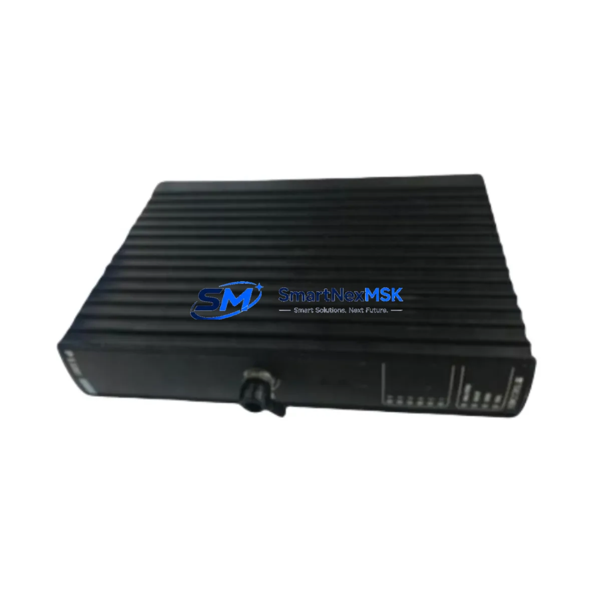
Triconex RO3451 Maintenance-Ready Spare for Tricon Automation
The Triconex RO3451 is a 32-channel relay output module engineered for the Tricon Triple Modular Redundant (TMR) safety PLC platform — one of the most widely deployed SIL 3-certified control architectures in oil & gas, petrochemical, power generation, and critical process industries. As a maintenance-ready original spare, the RO3451 is designed to support rapid field replacement, minimize unplanned downtime, and sustain the integrity of safety instrumented systems (SIS) during both scheduled turnarounds and emergency recovery scenarios.
For maintenance engineers managing aging Tricon systems, the RO3451 represents a critical line item in any spare parts inventory strategy. Its relay output architecture provides dry-contact switching capability for final control elements, ESD valves, motor starters, and alarm annunciators — making it indispensable in safety loops where output signal integrity directly affects process safety. Procurement engineers sourcing this module should verify compatibility with the installed Tricon chassis generation, backplane revision, and firmware baseline before deployment.
Spare Maintenance Table
| Parameter | Specification |
|---|---|
| Part Number / SKU | RO3451 |
| Brand | Triconex (Schneider Electric) |
| Series | Tricon TMR Safety PLC |
| Module Type | 32-Channel Relay Output Module |
| Output Type | Dry-contact relay, Form A (SPST-NO) |
| Safety Integrity Level | SIL 3 (IEC 61511 / IEC 61508) |
| Architecture | Triple Modular Redundant (TMR) |
| Rated Voltage | 24 VDC / 120 VAC / 240 VAC (load-side) |
| Contact Rating | 2A @ 30 VDC / 0.5A @ 120 VAC |
| Backplane Compatibility | Tricon Main Chassis, Expansion Chassis |
| Operating Temperature | 0°C to 60°C |
| Weight | 2,750 g (approx.) |
| Origin | USA |
| Condition | Original, tested before shipment |
| Warranty | 12 Months |
| Application Environment | Oil & Gas, Petrochemical, Power, Chemical Processing |
| Maintenance Recommendation | Inspect relay contacts, verify TMR voting logic, confirm backplane seating annually |
Maintenance Planning for Continuous Operation
When scheduling replacement of the RO3451 relay output module, a thorough inspection of the surrounding control cabinet and associated I/O infrastructure is essential to prevent cascading failures and ensure the safety loop is fully restored. Maintenance engineers should treat the RO3451 replacement as a trigger for a broader system health check.
Begin by verifying the Tricon Power Module (PM3100 or PM3200) supplying the chassis — relay output modules are sensitive to power rail fluctuations, and a degraded power module can cause intermittent relay chatter or false trip signals. Simultaneously, inspect the Tricon Main Processor Module (MP3008 or MP3010) for firmware version alignment, as mismatched firmware between the processor and I/O modules can cause communication faults post-replacement.
Check the Tricon Communication Module (TCM) or Triconex Enhanced Intelligent Communication Module (EICM) for active diagnostics — a relay output fault is sometimes a symptom of upstream communication degradation rather than a failed module itself. If the system uses a Tricon Digital Input Module (DI3401 or DI3416) in the same safety loop, verify that input signal states are consistent with expected process conditions before re-energizing the output relay.
For systems with mixed analog and digital I/O, inspect adjacent Tricon Analog Input Modules (AI3351 or AI3361) for signal drift — particularly in high-temperature or high-vibration environments where connector fatigue is common. Terminal blocks and field wiring terminations on the Tricon Field Termination Assembly (FTA) should be re-torqued and inspected for corrosion, especially in offshore or humid environments.
If the RO3451 is part of an ESD or fire-and-gas (F&G) loop, also verify the status of associated signal isolators and barriers (such as Zener barriers or galvanic isolators) in the field junction box. Fuse integrity on the output side of the relay module — typically housed in the FTA or a dedicated fuse terminal block — should be confirmed before loop testing. Finally, if the plant uses a Triconex Trident or Trident MP system in parallel for redundancy, cross-check the voting logic configuration to ensure the replacement module is correctly enrolled in the TMR architecture.
Site Replacement Workflow
Replacing the RO3451 in a live Tricon TMR system requires adherence to the site’s Management of Change (MOC) procedure and the Triconex hot-swap protocol. Because the Tricon architecture supports online module replacement without a full system shutdown, downtime can be minimized — but only if the replacement module is pre-verified and the field loop is properly isolated.
Step 1 — Pre-Replacement Verification: Confirm the replacement RO3451 SKU matches the installed revision. Check the module label for hardware revision suffix (e.g., RO3451 Rev C vs. Rev D) and cross-reference with the Triconex compatibility matrix for your chassis and firmware version. Our modules are tested and shipped with a functional verification report.
Step 2 — Field Loop Isolation: Coordinate with the control room to place the affected output channel(s) in manual override or bypass mode via the Triconex TriStation 1131 programming environment. Confirm bypass status on the Tricon Safety Manager (TSM) HMI or SCADA display before proceeding.
Step 3 — Module Extraction and Insertion: Follow the Triconex hot-swap procedure — release the module locking lever, extract the RO3451 from the chassis slot, and insert the replacement module firmly until the backplane connector is fully seated. The TMR system will automatically re-synchronize the new module within the voting architecture.
Step 4 — Loop Test and Reinstatement: Perform a point-to-point loop test on all 32 output channels. Verify relay energization and de-energization against the process cause-and-effect matrix. Remove the bypass, confirm normal operation on the HMI, and update the maintenance log with the replacement date, module serial number, and technician sign-off.
This workflow applies equally to planned turnaround replacements and emergency recovery scenarios. Stocking a minimum of one RO3451 spare per Tricon chassis in your on-site spare parts inventory is recommended to support a sub-4-hour recovery target for critical safety loops.
Spare Parts Support FAQ
Q1: Is the RO3451 compatible with all Tricon chassis generations?
The RO3451 is designed for the Tricon TMR platform and is compatible with standard Tricon main chassis and expansion chassis configurations. Compatibility depends on the chassis hardware revision and installed firmware version. We recommend providing your chassis model and firmware baseline when ordering so our technical team can confirm compatibility before shipment.
Q2: What testing is performed before the RO3451 is shipped?
Each RO3451 unit undergoes functional verification prior to dispatch, including relay contact continuity testing, backplane connector inspection, and visual examination for physical damage. A test report is available upon request. All units are shipped with anti-static packaging and are covered by a 12-month warranty from the date of delivery.
Q3: Can the RO3451 replace older relay output module variants in legacy Tricon systems?
In many cases, yes. The RO3451 is a direct replacement candidate for earlier Triconex relay output modules used in legacy Tricon systems. However, hardware revision differences may affect pin-out or firmware handshake behavior. Our team can assist with cross-reference validation and provide documentation to support your site’s MOC process.
Q4: What is the recommended spare parts stocking strategy for the RO3451?
For critical SIL 3 safety systems, industry best practice recommends maintaining a minimum of one hot-spare RO3451 per installed chassis on-site, with an additional unit held at the regional warehouse for multi-site operations. Given the long lead times associated with OEM procurement channels, sourcing from a specialist spare parts supplier with immediate stock availability — and a 12-month warranty — significantly reduces exposure to extended downtime risk.
© 2026 SMARTNEXMSK. All rights reserved.
Original Source: https://smartnexmsk.com
Contact: sales@smartnexmsk.com | +86 18259474341