
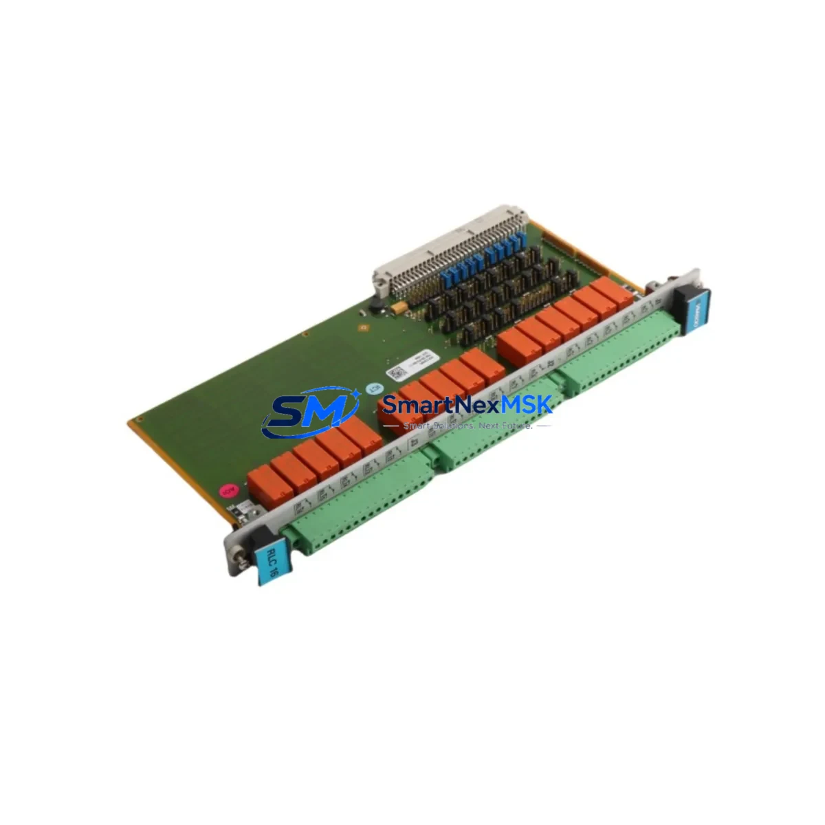
Vibro-Meter VM600 RLC16 200-570-000-111 Spare VM600: Relay Output Card Replacement for Industrial Downtime Control
The Vibro-Meter VM600 RLC16 (P/N 200-570-000-111) is a 16-channel relay output card designed for the VM600 rack-based machinery protection and condition monitoring system. As a critical output interface between the VM600 chassis and plant-level protection logic, the RLC16 drives relay contacts that trigger alarms, shutdowns, and interlock signals across rotating machinery trains — including turbines, compressors, pumps, and generators. When this card fails or degrades, the entire protection loop is compromised, exposing the machine to undetected fault conditions and potential catastrophic failure.
Sourcing a verified original spare — not a refurbished substitute — is the only reliable path to restoring protection system integrity. This listing supplies a genuine Vibro-Meter VM600 RLC16 200-570-000-111, tested prior to shipment, backed by a 12-month warranty, and available for fast global dispatch to minimize your maintenance window.
Spare Maintenance Table
| Parameter | Specification / Detail |
|---|---|
| Part Number | 200-570-000-111 |
| Model | VM600 RLC16 |
| Brand | Vibro-Meter (Meggitt) |
| Series | VM600 Machinery Protection System |
| Function | 16-Channel Relay Output Card |
| Output Channels | 16 independent relay contacts |
| Relay Type | Dry contact, configurable NO/NC |
| Compatibility | VM600 rack chassis; compatible with AMC8, MPC4, IOC4T, RPS6U modules |
| Application | Turbine, compressor, pump, and generator protection systems |
| Installation | Rack-mount card; hot-swap capable in supported VM600 configurations |
| Operating Environment | Industrial control room / MCC cabinet; standard IEC 61010 conditions |
| Origin | Switzerland (Vibro-Meter SA) |
| Condition | Original, new or fully tested surplus |
| Pre-shipment Test | Functional relay actuation and continuity verification |
| Warranty | 12 Months |
| Lead Time | In stock — ships within 2 business days |
Maintenance Planning for Continuous Operation
Maintenance engineers replacing the VM600 RLC16 200-570-000-111 should treat the intervention as an opportunity for a broader VM600 rack inspection. The RLC16 does not operate in isolation — its relay outputs are driven by upstream measurement and processing cards, and its contacts feed downstream field wiring, terminal blocks, and interlock circuits. A systematic check of the following components during the same maintenance window significantly reduces the risk of repeat downtime:
Begin with the VM600 AMC8 Absolute Measurement Card, which processes vibration and position signals before passing alarm and danger thresholds to the RLC16. A degraded AMC8 can produce erratic relay behavior that is misdiagnosed as an RLC16 fault. Similarly, inspect the VM600 MPC4 Machine Protection Card for firmware version alignment and relay mapping consistency after any card swap.
The VM600 RPS6U Rack Power Supply is another high-priority check: relay output cards are sensitive to power rail instability, and a marginal RPS6U can cause intermittent relay chatter or contact welding under load. Verify output voltage rails and ripple levels before reinstalling the RLC16.
On the field wiring side, inspect the VM600 IOC4T I/O Connector Card and its associated terminal blocks for oxidation, loose ferrules, or insulation breakdown — particularly in high-vibration or high-humidity environments. Relay contact wiring to DIN rail terminal strips and interposing relay modules in the control cabinet should be torque-checked and visually inspected for arc damage.
If the VM600 system communicates with a DCS or safety PLC via Modbus RTU or Profibus DP, verify that the communication module — such as the VM600 CMC16 Communication Card — is correctly mapped to the new relay configuration. Relay output assignments may need to be re-confirmed in the VM600 rack configuration software after card replacement.
For sites running legacy VM600 racks alongside newer condition monitoring platforms, consider stocking the VM600 XMC16 Expansion Module and a spare VM600 backplane connector assembly as part of your long-term spares strategy. Backplane connector wear is a common root cause of intermittent card faults in systems with high card swap frequency.
Finally, if the plant uses signal isolators or galvanic barriers between the VM600 relay outputs and the DCS input cards, inspect these devices for leakage current or threshold drift — conditions that can cause false trips even after a successful RLC16 replacement.
Site Replacement Workflow
Step 1 — Pre-replacement verification: Confirm the failed card P/N as 200-570-000-111 against the rack label and VM600 configuration file. Cross-check relay output assignments in the system documentation before removal to avoid rewiring errors.
Step 2 — Safe isolation: Notify the control room and place the affected machine in a safe state or bypass mode per your site MOC procedure. Do not remove the RLC16 under live relay load without confirming bypass status.
Step 3 — Card extraction and inspection: Remove the RLC16 using the card ejector handles. Inspect the backplane connector pins for damage or contamination. Clean with isopropyl alcohol if required before inserting the replacement card.
Step 4 — Replacement installation: Insert the new VM600 RLC16 200-570-000-111 firmly until the front panel latch engages. The VM600 rack will auto-detect the card; allow 30–60 seconds for initialization before checking relay status LEDs.
Step 5 — Functional test: Using the VM600 rack software or front-panel test function, actuate each relay channel and verify correct contact state at the field terminal. Confirm alarm and danger relay outputs match the pre-replacement configuration.
Step 6 — Return to service: Remove bypass, restore normal monitoring mode, and document the replacement in the maintenance management system with the new card serial number and test results.
This workflow is compatible with both hot-swap and cold-swap VM600 rack configurations and supports direct replacement of earlier RLC16 variants without firmware changes in most VM600 rack revisions.
Spare Parts Support FAQ
Q1: Is this VM600 RLC16 200-570-000-111 a direct replacement for older RLC16 variants?
Yes. The 200-570-000-111 is the current production part number for the VM600 RLC16 and is backward compatible with earlier VM600 rack revisions. No firmware update or rack reconfiguration is required in standard replacement scenarios. Confirm your rack firmware version if you are running a VM600 system older than 2005.
Q2: How is the card tested before shipment?
Each VM600 RLC16 200-570-000-111 unit undergoes functional relay actuation testing across all 16 channels, contact continuity verification, and visual inspection for connector and PCB integrity. A test report is available upon request for critical plant applications.
Q3: What is the recommended spare parts stocking strategy for VM600 relay output cards?
For plants with two or more VM600 racks, we recommend maintaining a minimum of one RLC16 per rack as a cold spare. For single-rack critical applications (e.g., main turbine protection), consider a hot-spare rack slot or a pre-configured replacement card stored in the control room. Relay output cards have a typical service life of 10–15 years; proactive replacement at the 10-year mark reduces unplanned failure risk.
Q4: What warranty and after-sales support is provided?
All units are covered by a 12-month warranty against manufacturing defects and functional failure under normal operating conditions. If a unit fails within the warranty period, we provide a replacement or full refund. Long-term supply agreements and multi-unit pricing are available for MRO procurement teams managing extended VM600 fleet maintenance programs.
© 2026 SMARTNEXMSK. All rights reserved.
Original Source: https://smartnexmsk.com
Contact: [email protected] | +86 18259474341