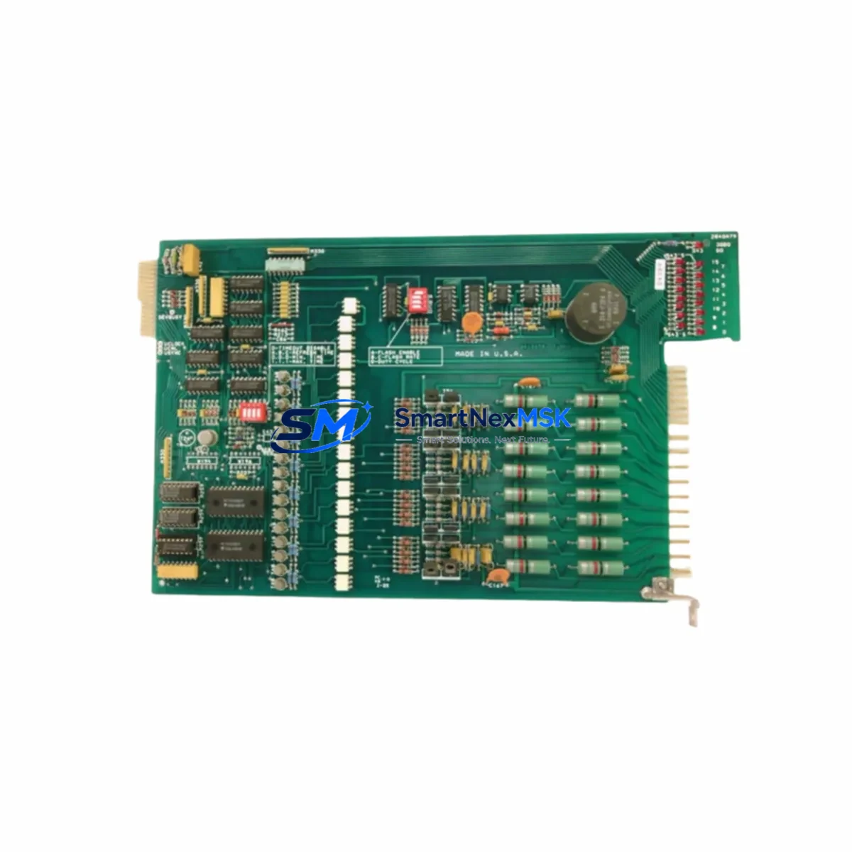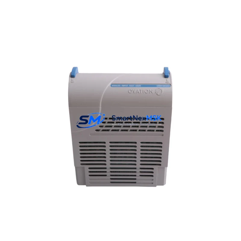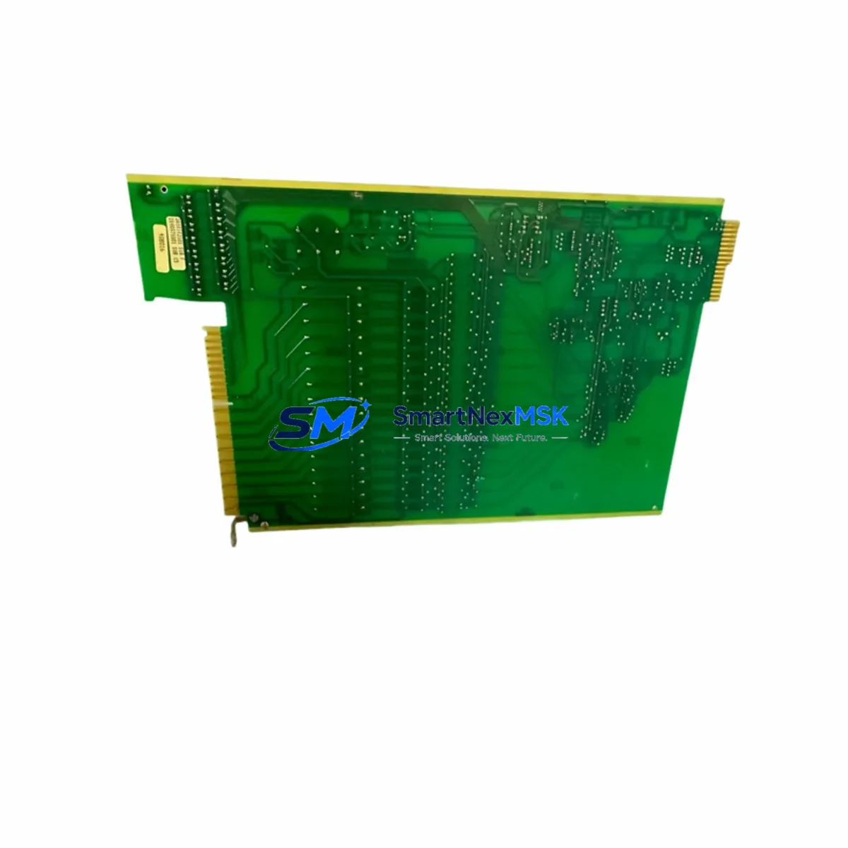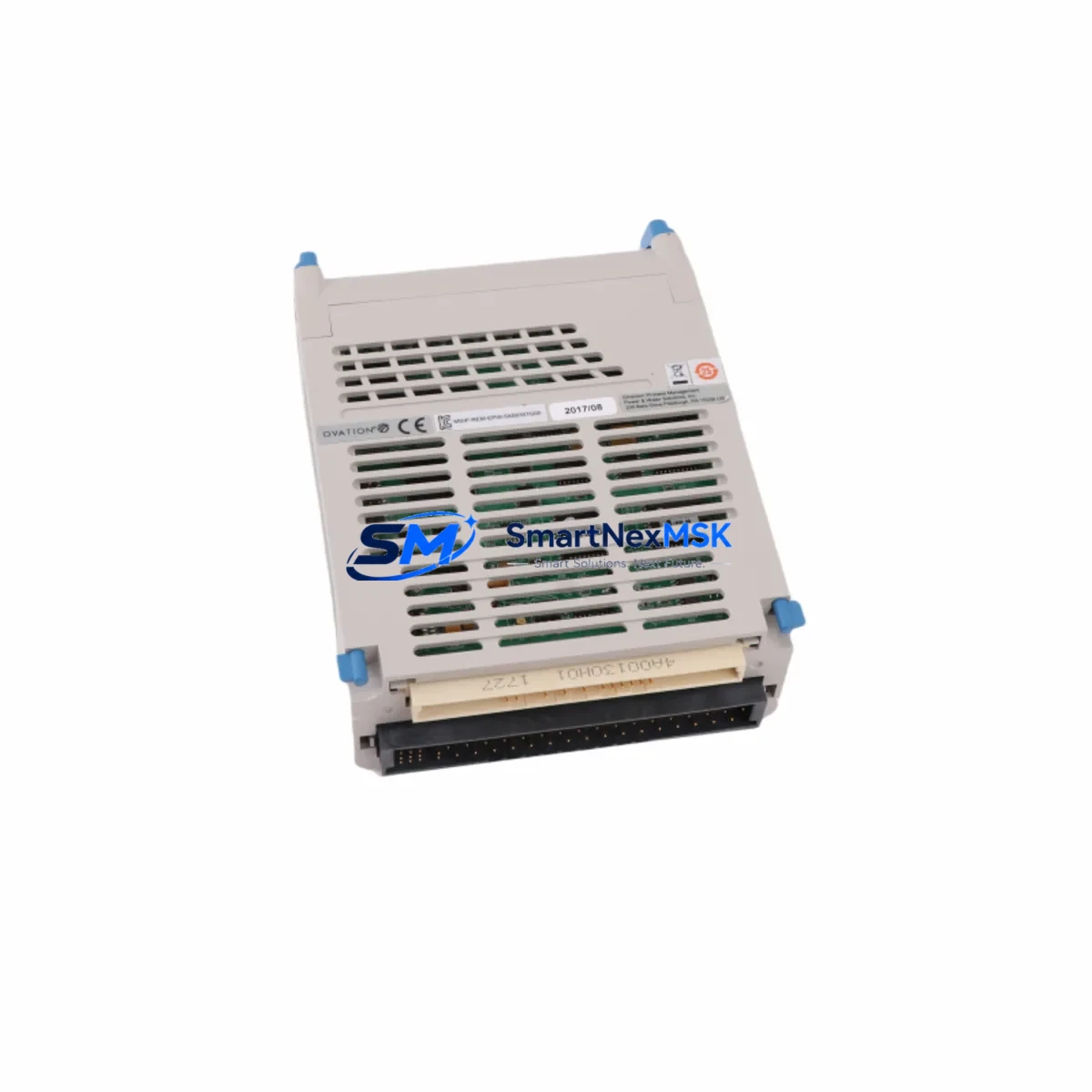
Westinghouse 5X00357G05 Retrofit-Ready Controller for WDPF Series Control Systems
The Westinghouse 5X00357G05 is a programmable controller module engineered for seamless integration into WDPF (Westinghouse Distributed Processing Family) distributed control architectures. As legacy WDPF installations approach end-of-life and original spare parts become increasingly scarce, the 5X00357G05 serves as a critical retrofit solution for facilities seeking to extend operational continuity without committing to a full platform migration. Whether you are replacing a failed unit on an active production line, upgrading a control cabinet to meet current safety standards, or executing a phased modernization of an aging DCS infrastructure, this module delivers the compatibility and reliability that industrial engineers demand.
Sourced from verified inventory channels and subjected to pre-shipment functional testing, each 5X00357G05 unit is confirmed operational before dispatch. All units are backed by a 12-month warranty covering manufacturing defects and functional failures under normal operating conditions. Global logistics support ensures delivery to refineries, power generation facilities, chemical processing plants, and heavy manufacturing sites across Asia, Europe, the Middle East, and the Americas.
Upgrade Compatibility Table
| Parameter | Details |
|---|---|
| SKU / Part Number | 5X00357G05 |
| Brand / OEM | Westinghouse |
| Compatible Platform | WDPF Series Distributed Control System |
| Module Type | Programmable Controller Module |
| Backplane Interface | WDPF standard backplane bus; verify slot addressing before installation |
| Communication Protocol | WDPF proprietary network; confirm firmware revision compatibility with existing WDPF nodes |
| Power Supply Requirement | Confirm rack power capacity (typically 24 VDC or 5 VDC bus); verify against existing 5X00095G01 or equivalent PSU rating |
| Terminal / Wiring | Matches original WDPF field termination assemblies; no rewiring required for direct replacement |
| Replacement Recommendation | Direct drop-in for failed or end-of-life 5X00357G05 units; cross-reference with 5X00357G01–G04 variants for partial compatibility |
| Commissioning Notes | Reload node configuration from WDPF Engineer Workstation; verify I/O map and module address assignment post-swap |
| Warranty | 12 months from date of shipment |
| Pre-Shipment Testing | Functional verification completed; test report available on request |
Retrofit Planning for Existing Automation Systems
Successful integration of the 5X00357G05 into an operating WDPF environment requires systematic pre-installation planning. Begin by auditing the existing rack configuration: identify the chassis model (such as the WDPF standard 19-inch rack assembly), confirm the total number of occupied slots, and document the current module address assignments to avoid address conflicts after the swap. The WDPF system assigns node addresses at the hardware level, and any mismatch between the replacement module’s configured address and the existing network map will result in communication faults across the WDPF data highway.
Power budget verification is a mandatory step before installation. Calculate the aggregate current draw of all modules installed in the rack — including I/O modules such as the 5X00119G01 analog input module and 5X00121G01 digital output module — and confirm that the rack power supply unit has sufficient headroom to support the 5X00357G05 without triggering overcurrent protection. If the existing PSU is operating near capacity, consider upgrading to a higher-rated supply before proceeding.
Field wiring connected to the WDPF termination assemblies should be inspected and labeled prior to module removal. The 5X00357G05 uses the same terminal block footprint as its predecessors, so field cables can remain connected to the termination panel during the swap, significantly reducing reconnection time and the risk of wiring errors. After physical installation, use the WDPF Engineer Workstation software to reload the node’s configuration database, verify the I/O channel assignments, and confirm that all process variables are scanning correctly before returning the loop to automatic control.
For facilities also upgrading their human-machine interface layer, ensure that HMI display pages referencing the replaced controller node are updated to reflect any tag name or address changes. Systems running Ovation DCS or transitioning from WDPF to Ovation should additionally verify that the communication gateway — often a WDPF/Ovation bridge module — correctly maps the 5X00357G05 node data to the Ovation historian and alarm management system. Communication cables connecting the WDPF data highway, including coaxial or fiber segments, should be tested for signal integrity before commissioning the replacement module.
Where I/O expansion is part of the modernization scope, the 5X00357G05 can coexist in the same rack with WDPF-compatible expansion modules, including additional analog input cards, RTD input modules, and pulse input modules. Facilities planning a phased migration to a modern DCS platform should document the current I/O list, loop diagrams, and cause-and-effect matrices before beginning any hardware changes, as this documentation will be essential for programming the replacement controller and validating the migrated control logic.
Downtime Control During System Migration
Minimizing unplanned downtime during a controller replacement is the primary operational concern for any facility running continuous or semi-continuous processes. The 5X00357G05 replacement procedure is designed to be executed during a planned maintenance window, with the target process loop placed in manual control mode at the DCS operator station before the module is removed. This preserves field device states — control valves, motor starters, and interlock relays — in their last commanded positions while the swap is performed.
Before powering down the rack slot, export a backup of the node configuration from the WDPF Engineer Workstation. This backup file contains the full I/O configuration, scaling parameters, alarm limits, and control block definitions associated with the 5X00357G05 node. Retaining this backup ensures that if the replacement module requires reconfiguration, the original parameters can be restored without manual re-entry, which is a significant source of commissioning errors in legacy DCS environments.
Physical replacement of the module typically requires less than fifteen minutes for a trained technician familiar with the WDPF rack architecture. After seating the 5X00357G05 in the correct slot and securing the module latch, restore rack power and observe the module’s status indicators. A healthy module will complete its self-diagnostic sequence and establish communication on the WDPF data highway within approximately sixty seconds. Reload the node configuration from the Engineer Workstation, verify that all I/O channels are scanning and returning valid process values, and confirm alarm states before returning the loop to automatic control. Total planned downtime for a straightforward replacement — excluding pre-work and documentation — is typically under two hours.
For facilities where even brief interruptions are unacceptable, a hot-standby configuration using a redundant WDPF controller pair can be considered. In redundant architectures, the standby module assumes control automatically upon detection of a primary module fault, allowing the failed 5X00357G05 to be replaced without process interruption. Confirm with your WDPF system documentation whether your installed rack supports redundant controller operation before relying on this approach.
Retrofit Support FAQ
Q: Is the 5X00357G05 a direct replacement for all WDPF Series controller variants?
A: The 5X00357G05 is a direct replacement for units sharing the same part number suffix (G05). Cross-compatibility with G01 through G04 variants depends on firmware revision and rack slot configuration. We recommend providing your existing module’s full part number and firmware label when placing an order so our technical team can confirm compatibility before shipment.
Q: What commissioning steps are required after installing the replacement module?
A: After physical installation, reload the node configuration from the WDPF Engineer Workstation, verify module address assignment, confirm I/O channel scanning, and check communication status on the WDPF data highway. Place affected control loops in manual mode during the swap and return to automatic only after all process variables are confirmed valid. A pre-shipment test report is available on request to support your site acceptance procedure.
Q: Can the 5X00357G05 be used in a system that is being migrated from WDPF to a modern DCS platform?
A: Yes. The 5X00357G05 is commonly used as an interim replacement to restore system stability while a phased migration is planned and executed. It maintains full compatibility with the existing WDPF data highway, field termination assemblies, and Engineer Workstation software, allowing the migration to proceed on a controlled schedule without forcing an emergency platform change.
Q: What does the 12-month warranty cover?
A: The warranty covers manufacturing defects and functional failures under normal operating conditions for twelve months from the date of shipment. Each unit undergoes pre-shipment functional testing, and a test report is available on request. Warranty claims are processed promptly, with replacement units dispatched upon confirmation of the defect to minimize impact on your operations.
© 2026 SMARTNEXMSK. All rights reserved.
Original Source: https://smartnexmsk.com
Contact: [email protected] | +86 18259474341