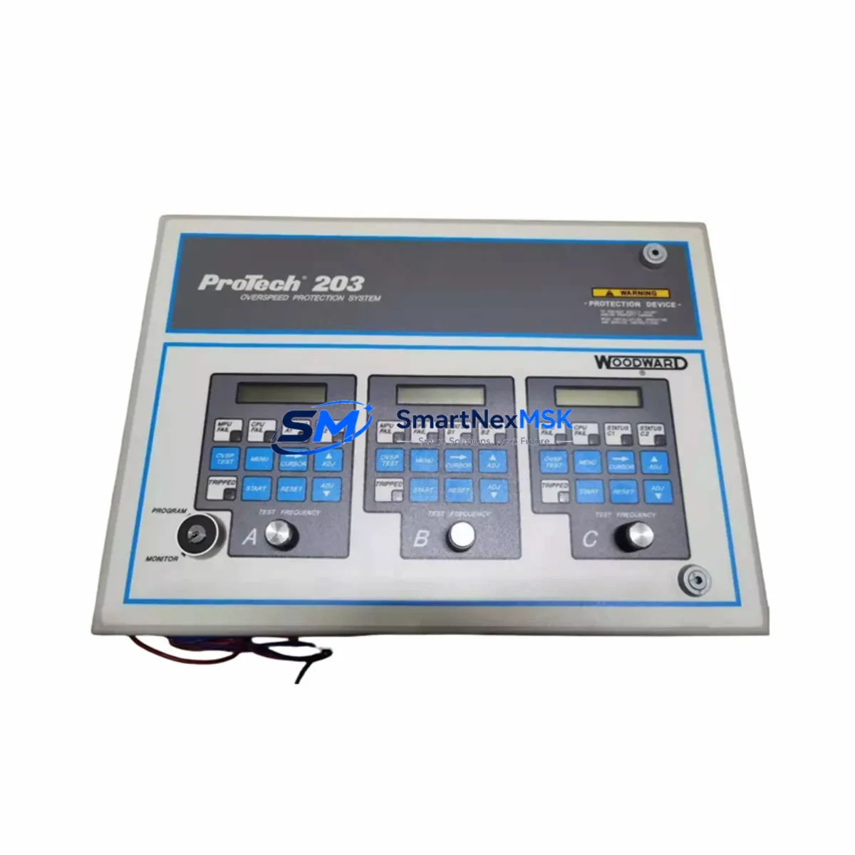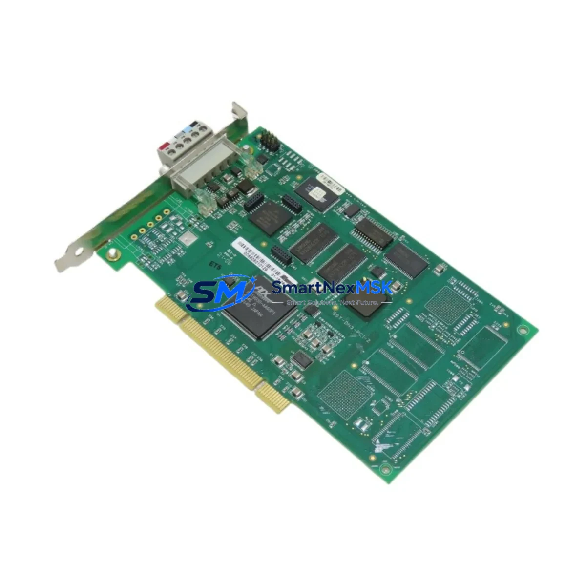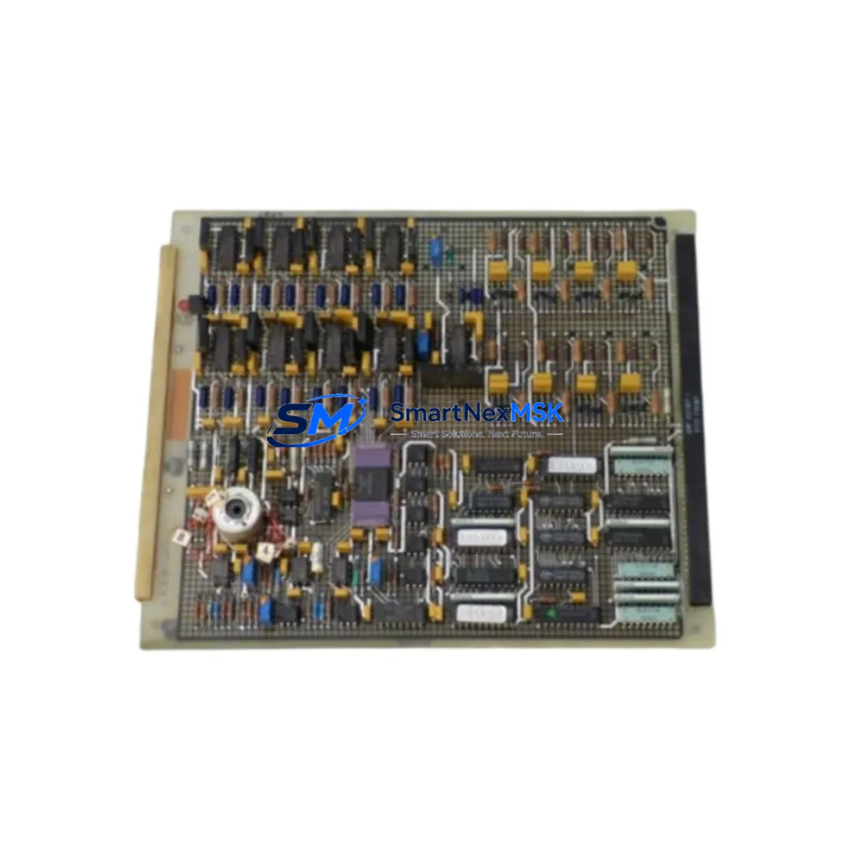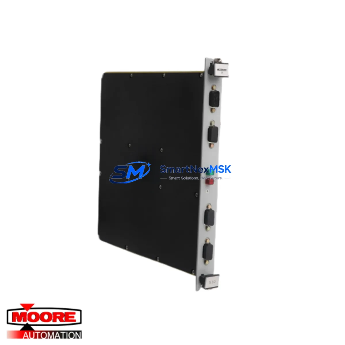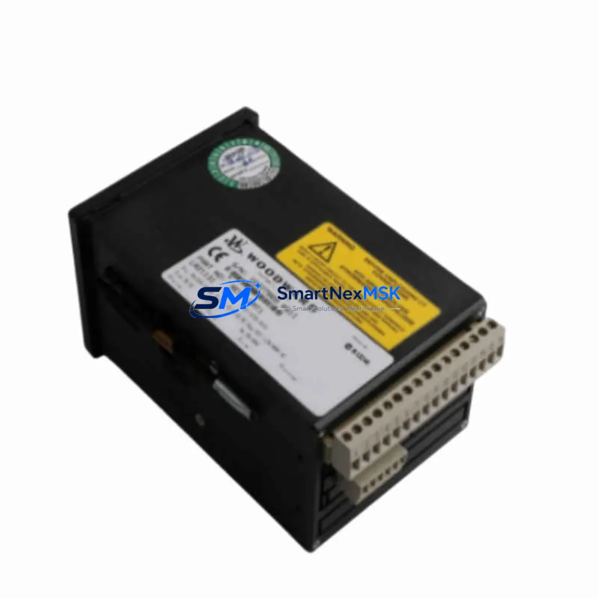
WOODWARD UMT1 UMT145B A3 LR20523 Retrofit-Ready Governor Module for UMT Series Control Systems
The WOODWARD UMT1 UMT145B A3 LR20523 is a retrofit-ready governor control module engineered for seamless integration into existing UMT Series turbine and engine control systems. As legacy WOODWARD governor platforms approach end-of-life and original spare parts become increasingly scarce, this module provides a verified drop-in replacement path that preserves existing control logic, terminal wiring, and communication architecture — minimizing engineering rework and unplanned downtime during system modernization.
Whether you are replacing a failed unit in an emergency shutdown scenario, executing a planned control cabinet upgrade, or migrating from an obsolete WOODWARD platform to a current-generation governor architecture, the UMT1 UMT145B A3 LR20523 is stocked, tested, and ready for immediate dispatch. Each unit undergoes pre-shipment functional verification and is backed by a 12-month warranty covering manufacturing defects and operational failures under normal service conditions.
Upgrade Compatibility Table
| Parameter | Details |
|---|---|
| Compatible Series | WOODWARD UMT Series (UMT1, UMT145, UMT145B variants) |
| Module Function | Governor CPU / Control Module |
| Replaces | UMT1, UMT145B A3, LR20523 and functionally equivalent legacy part numbers |
| Backplane Interface | Compatible with standard UMT Series rack and backplane connectors |
| Communication Protocol | Supports WOODWARD proprietary serial communication; verify link configuration with existing HMI or SCADA |
| Power Supply Requirement | Confirm 24 VDC or 120/240 VAC supply capacity at control cabinet before installation |
| Terminal Wiring | Direct terminal-for-terminal replacement; verify actuator feedback and speed sensor wiring polarity |
| Module Address | Set module address via DIP switch or configuration tool to match existing system map |
| Program Compatibility | Existing governor application software is retained on host controller; no reprogramming required in most retrofit scenarios |
| HMI Screen Compatibility | Existing HMI tag mapping remains valid; verify alarm and setpoint display after commissioning |
| Commissioning Requirement | Speed reference calibration, droop setting verification, and actuator stroke test recommended post-installation |
| Warranty | 12-Month Warranty — covers manufacturing defects and operational failures under normal service conditions |
| Pre-Shipment Testing | Full functional verification performed before dispatch |
| Origin | China (CN) |
Retrofit Planning for Existing Automation Systems
Successful retrofit of the WOODWARD UMT1 UMT145B A3 LR20523 begins with a thorough audit of the existing control cabinet. Before removing the failed or obsolete module, engineers should document the current terminal block wiring layout, confirm the power supply module output capacity — typically a WOODWARD 24 VDC regulated supply or equivalent — and photograph all actuator feedback connections and speed sensor inputs. This documentation becomes the reference baseline for post-installation verification.
In systems where the UMT1 governor module interfaces with a WOODWARD 2301A or 2301D load sharing and speed control unit, the communication link between the governor and the load controller must be re-established and verified after module swap. Similarly, if the control system includes a WOODWARD MicroNet or ProTech series safety shutdown module, the trip relay wiring and shutdown logic sequence should be confirmed against the original system schematic before returning the unit to service.
For installations that use a WOODWARD 505 or 505E digital governor as the primary speed controller in tandem with the UMT module, engineers should verify that the analog speed reference signal and the 4–20 mA actuator output remain within calibrated range after replacement. The WOODWARD GAP (Graphical Application Programmer) software tool is recommended for reviewing and, if necessary, adjusting the application block diagram without modifying the core control logic.
I/O expansion requirements should also be assessed during retrofit planning. If the existing system relies on a WOODWARD I/O expansion module or a third-party discrete I/O terminal block assembly mounted in the same control cabinet, confirm that the new UMT1 UMT145B A3 LR20523 module correctly addresses all mapped I/O points. Address conflicts between the replacement module and adjacent rack-mounted modules — such as analog input modules for thermocouple or RTD signals — must be resolved before energizing the system.
Where the control system includes a local HMI panel — such as a WOODWARD Easygen series genset controller display or a third-party operator interface terminal — verify that all governor status tags, alarm setpoints, and speed reference displays are correctly mapped to the replacement module’s output registers. In some legacy installations, the HMI configuration file may reference the original module’s firmware version; a firmware compatibility check is recommended before final commissioning.
Programming cables and configuration adapters — including the WOODWARD Watch Window software interface cable — should be available on-site during commissioning to allow real-time monitoring of governor response, speed droop, and actuator position feedback during initial run-up. This is particularly important in gas turbine, steam turbine, and diesel generator applications where governor response tuning directly affects grid synchronization performance.
Downtime Control During System Migration
Minimizing production downtime during a governor module replacement requires advance preparation and a structured changeover sequence. The recommended approach is to pre-configure and bench-test the WOODWARD UMT1 UMT145B A3 LR20523 replacement module off-line before the scheduled maintenance window. Using the WOODWARD Watch Window or GAP configuration tool, verify that all parameter settings — including speed reference, droop percentage, actuator gain, and PID tuning values — match the documented settings from the outgoing module.
During the physical swap, the control system should be placed in manual control mode or transferred to a redundant control path where available, ensuring that the prime mover remains under safe supervisory control throughout the module exchange. Terminal block wiring should be transferred one circuit at a time, with each connection verified against the wiring diagram before proceeding to the next. This sequential approach prevents cross-wiring errors that could cause actuator runaway or false shutdown signals on restart.
After installation, a controlled restart sequence — beginning with a no-load speed run to verify governor stability before connecting to the load — is strongly recommended. Speed droop, isochronous response, and load acceptance behavior should all be confirmed within specification before returning the unit to full production service. Retaining the original program logic and parameter file throughout the retrofit process ensures that the existing control strategy is preserved, protecting the investment in the original system engineering and eliminating the need for a full recommissioning cycle.
Retrofit Support FAQ
Q1: Is the WOODWARD UMT1 UMT145B A3 LR20523 a direct drop-in replacement for the original module?
In the majority of UMT Series installations, yes. The module is designed to match the original backplane connector, terminal block layout, and communication interface of the UMT1 and UMT145B A3 platform. However, customers are advised to confirm the exact hardware revision and firmware version of the outgoing module against the replacement unit specification sheet before installation, particularly in systems with customized I/O mapping or non-standard actuator configurations.
Q2: What commissioning steps are required after installing the replacement module?
After physical installation and wiring verification, the following commissioning steps are recommended: (1) power-on self-test confirmation, (2) speed sensor signal verification, (3) actuator feedback calibration, (4) speed reference and droop setting confirmation using Watch Window or equivalent configuration tool, and (5) a controlled no-load run-up to verify governor stability before load connection. Full commissioning documentation should be retained for maintenance records.
Q3: Can the existing application program be retained when replacing the module?
Yes. In standard retrofit scenarios, the application program resides on the host controller or is stored in non-volatile memory within the module itself. The existing program logic, setpoints, and parameter values are preserved during module replacement. If the outgoing module’s memory is inaccessible due to failure, a backup parameter file — ideally maintained as part of the site’s preventive maintenance records — can be used to restore the configuration to the replacement unit.
Q4: What does the 12-month warranty cover, and what is the dispatch timeline?
The 12-month warranty covers manufacturing defects and operational failures arising under normal service conditions from the date of shipment. It does not cover damage resulting from incorrect installation, overvoltage events, or unauthorized modification. Units are dispatched following pre-shipment functional verification. Standard lead time is 3–7 business days for stocked units, with expedited dispatch available for urgent breakdown requirements. Contact our sales team to confirm current stock availability and shipping options for your region.
© 2026 SMARTNEXMSK. All rights reserved.
Original Source: https://smartnexmsk.com
Contact: [email protected] | +86 18259474341