
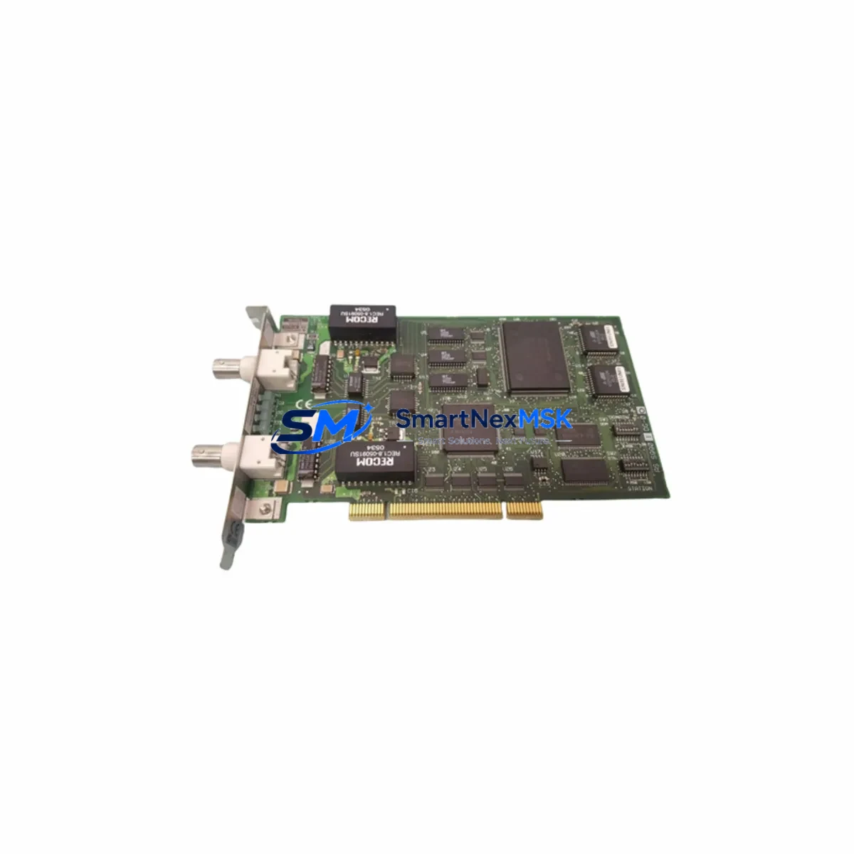
YOKOGAWA VF701-S3 Retrofit-Ready Communication Card for VF700 Series Control Systems
The YOKOGAWA VF701-S3 (also referenced as VF701-S1) is a plug-in communication option card engineered for the YOKOGAWA VF700 series variable frequency drive platform. Designed to support both PROFIBUS-DP and Modbus RTU protocols on a single hardware footprint, this card enables seamless integration of legacy VF700 drives into modern distributed control architectures. For facilities managing aging automation infrastructure — whether running a CENTUM VP DCS backbone, a STARDOM network controller environment, or a third-party SCADA system — the VF701-S3 provides a validated, drop-in retrofit path that avoids the cost and risk of full drive replacement.
Our stock is sourced from authorized distribution channels and subject to full incoming inspection before dispatch. Every unit ships with a 12-month warranty covering manufacturing defects and functional failure under normal operating conditions. Lead time is typically 3–7 business days for in-stock units, with expedited options available for urgent plant shutdowns or unplanned failures.
Upgrade Compatibility Table
| Parameter | VF701-S3 / VF701-S1 Specification |
|---|---|
| Compatible Drive Series | YOKOGAWA VF700 Series VFDs |
| Supported Protocols | PROFIBUS-DP (VF701-S3), Modbus RTU (VF701-S1) |
| Installation Interface | Option slot on VF700 drive front panel (tool-free card insertion) |
| Communication Baud Rate | Up to 12 Mbps (PROFIBUS-DP); up to 115.2 kbps (Modbus RTU) |
| Node Address Setting | Rotary switch on card face; configurable without drive power cycle |
| Backplane Compatibility | Direct slot mount — no adapter bracket or riser required |
| Replacement Scope | Direct drop-in for original VF701-S3 and VF701-S1 units |
| Retrofit Recommendation | Suitable for protocol migration from RS-485 point-to-point to PROFIBUS network topology |
| Commissioning Notes | Verify GSD file version in PLC/DCS project matches card firmware; re-download drive parameters after card swap |
| Warranty | 12 months from shipment date, covering manufacturing defects and functional failure |
Retrofit Planning for Existing Automation Systems
Integrating the VF701-S3 into an existing control system requires a structured pre-installation review. Before removing the legacy card, engineers should document the current PROFIBUS node address, verify the master PLC or DCS — commonly a YOKOGAWA STARDOM FCN/FCJ controller or a Siemens S7-300/S7-400 with CP 342-5 PROFIBUS master — has the correct GSD file loaded, and confirm that the drive’s parameter set has been backed up using YOKOGAWA’s DriveWizard software or an equivalent parameter cloning tool.
In retrofit projects involving multiple VF700 drives on a shared PROFIBUS segment, it is critical to power down only the target drive while keeping the segment termination resistors intact at both ends of the bus. Removing a node mid-segment without proper termination can cause communication faults across all remaining nodes. If the existing cabling uses older shielded twisted-pair without proper grounding at the PROFIBUS connector, this is an ideal time to upgrade to 9-pin D-sub connectors with integrated termination, such as those used with Siemens PROFIBUS plug 6ES7972-0BB52-0XA0 or equivalent.
For sites migrating from Modbus RTU (VF701-S1) to PROFIBUS-DP (VF701-S3), the migration plan should include updating the HMI faceplate — whether running on a YOKOGAWA ProSafe-RS safety controller interface, a Proface GP4000 series HMI, or a Weintek cMT panel — to reflect the new process variable addresses. Drive speed reference, output frequency, output current, fault status, and run/stop command registers will shift from Modbus holding register addresses to PROFIBUS process data objects (PDOs), requiring HMI tag remapping before go-live.
Power supply capacity in the control cabinet should also be verified. The VF700 drive’s internal 24 VDC auxiliary supply powers the option card slot; confirm that the total load from the VF701-S3 card, any installed I/O expansion modules such as the YOKOGAWA VF8-IO analog I/O option, and the drive’s own control board does not exceed the auxiliary supply rating. In older cabinets, a supplementary 24 VDC DIN-rail power supply — such as a Phoenix Contact QUINT or MEAN WELL DR series unit — may be required to maintain stable communication during drive acceleration transients.
Terminal wiring adaptation is straightforward for direct card replacements: the VF701-S3 uses the same option slot connector as the original card, so no rewiring of the drive’s main terminal block is required. However, if the PROFIBUS cable was previously routed through a cable gland directly to the old card’s screw terminals, plan for a short cable extension to reach the new card’s D-sub port. Label all conductors before disconnection and photograph the existing wiring for reference during reassembly.
Downtime Control During System Migration
Minimizing production downtime during a VF701-S3 card swap begins with pre-staging. Before the maintenance window opens, confirm that the replacement card has been bench-tested — apply 24 VDC to the drive in a test rig, insert the card, and verify that the PROFIBUS master detects the node and exchanges cyclic data correctly. This eliminates the risk of discovering a configuration mismatch during a live plant shutdown.
During the swap window, follow a structured sequence: isolate the drive from mains power and wait for the DC bus to discharge (typically 5 minutes for VF700 series), remove the option card by releasing the retention clip, insert the VF701-S3, restore power, and confirm the drive’s LED status indicators show normal communication. The PROFIBUS master — whether a YOKOGAWA CENTUM VP FCS field control station or a Rockwell ControlLogix with 1756-PROFIBUS scanner — should automatically re-establish cyclic communication within one bus scan cycle once the node is online.
To protect the original program logic, do not perform any drive parameter initialization (factory reset) during the card swap unless specifically required. The drive’s internal parameter memory is independent of the option card slot; swapping the card does not alter motor control parameters, acceleration/deceleration ramps, or protection thresholds. After the card is installed and communication is confirmed, perform a live comparison of key process values — output frequency, motor current, and speed reference — between the SCADA historian and the drive’s local display to verify data integrity before returning the drive to automatic control.
For multi-drive retrofit campaigns across a production line, a rolling replacement strategy — swapping one drive per shift while keeping adjacent drives in manual local control — allows continuous partial production and reduces the risk of a full-line stoppage. Document each completed swap in the plant’s maintenance management system (CMMS) with the card serial number, firmware version, and commissioning test results for traceability.
Retrofit Support FAQ
Q1: Is the VF701-S3 a direct replacement for the VF701-S1, or does it require additional configuration?
The VF701-S3 and VF701-S1 occupy the same physical option slot and use the same mechanical form factor, but they support different protocols — PROFIBUS-DP and Modbus RTU respectively. If you are replacing a VF701-S1 with a VF701-S3 to migrate from Modbus to PROFIBUS, you will need to update the master PLC/DCS configuration with the VF700 GSD file and remap process data addresses. If you are replacing like-for-like (VF701-S3 for VF701-S3), the swap is plug-and-play with no protocol reconfiguration required.
Q2: What commissioning steps are required after installing the VF701-S3?
After physical installation, set the PROFIBUS node address using the rotary switch on the card face to match the address configured in the master PLC or DCS. Power up the drive and confirm the card’s status LED indicates active communication. On the master side, verify that the VF700 node appears in the diagnostic view and that cyclic I/O data — speed reference, output frequency, run command, and fault status — is exchanging correctly. No special drive parameter changes are required for the card itself, but confirm that the drive’s communication option parameter group (typically parameter group P9 or equivalent in VF700 firmware) is set to enable the option slot.
Q3: How is wiring compatibility handled when replacing an older VF701-S1 card?
The PROFIBUS cable connects to the VF701-S3 via a standard 9-pin D-sub connector, while the VF701-S1 Modbus card uses RS-485 screw terminals. If migrating from Modbus to PROFIBUS, you will need to install a PROFIBUS cable with a D-sub connector to the card. Existing RS-485 wiring to the VF701-S1 screw terminals can be reused if converted to a D-sub plug, but it is recommended to install a dedicated PROFIBUS cable with proper shielding and termination for reliable high-speed communication.
Q4: What does the 12-month warranty cover, and what is the process for a warranty claim?
The 12-month warranty covers manufacturing defects and functional failure under normal operating conditions from the date of shipment. It does not cover damage caused by incorrect installation, overvoltage, moisture ingress, or unauthorized modification. To initiate a warranty claim, contact [email protected] with your order number, a description of the fault, and photos of the card and installation environment. We will arrange return shipping and either repair or replace the unit within 10 business days of receipt.
© 2026 SMARTNEXMSK. All rights reserved.
Original Source: https://smartnexmsk.com
Contact: [email protected] | +86 18259474341



