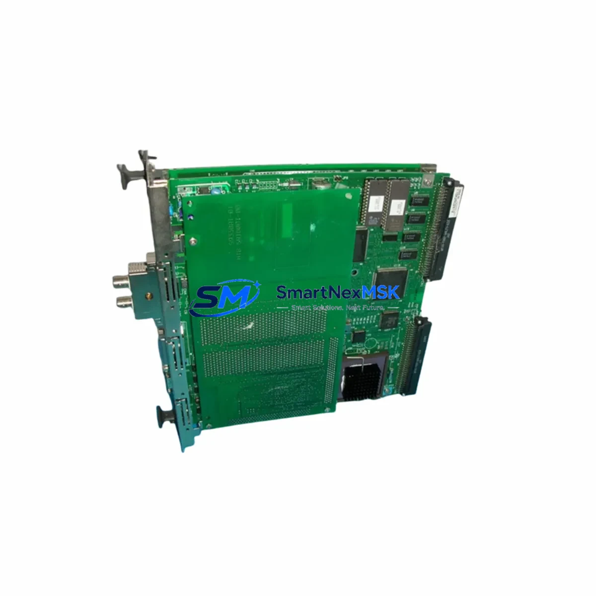
YOKOGAWA F3LC11-1F Maintenance-Ready Spare for FA-M3 Automation
The YOKOGAWA F3LC11-1F is a PC Link Communication Module designed for the FA-M3 modular PLC platform — one of YOKOGAWA’s most widely deployed process and factory automation controllers in petrochemical, power generation, pharmaceutical, and discrete manufacturing environments. As production facilities extend the operational life of FA-M3 systems beyond original vendor support windows, maintaining a verified stock of the F3LC11-1F becomes a critical element of any MRO (Maintenance, Repair & Operations) strategy.
This listing supplies an original, factory-sourced F3LC11-1F spare module, fully tested prior to shipment and backed by a 12-month warranty. Each unit is inspected for firmware integrity, connector condition, and communication function before dispatch, ensuring that your replacement module arrives ready for immediate installation — minimizing unplanned downtime and accelerating control system recovery.
Spare Maintenance Table
| Parameter | Specification / Detail |
|---|---|
| Part Number / SKU | F3LC11-1F |
| Manufacturer | YOKOGAWA Electric Corporation |
| Series / Platform | FA-M3 Modular PLC |
| Module Type | PC Link Communication Module |
| Communication Interface | PC Link (proprietary YOKOGAWA high-speed link bus) |
| Compatible CPU Modules | F3SP22, F3SP28, F3SP38, F3SP53, F3SP58, F3SP67, F3SP71, F3SP76 series |
| Backplane Compatibility | FA-M3 base units (F3BU04-0N, F3BU08-0N, F3BU16-0N and equivalents) |
| Operating Voltage | Supplied via FA-M3 backplane (5 VDC internal bus) |
| Operating Temperature | 0°C to 55°C |
| Storage Temperature | -20°C to 70°C |
| Humidity | 10% to 90% RH (non-condensing) |
| Country of Origin | Japan |
| Condition | Original / New-equivalent, pre-shipment tested |
| Warranty | 12 Months from date of shipment |
| Typical Application | PC-to-PLC data link, SCADA integration, supervisory data acquisition |
| Maintenance Recommendation | Inspect connector pins, verify link status LEDs, confirm PC Link master/slave addressing after installation |
Maintenance Planning for Continuous Operation
When a maintenance or procurement engineer schedules replacement of the F3LC11-1F, the scope of inspection should extend beyond the module itself. The FA-M3 control cabinet is an integrated system, and a communication fault at the PC Link layer often signals stress on adjacent components that share the same power rail, backplane slot, or data path.
Begin with the FA-M3 power supply module (such as the F3PU20-0S or F3PU30-0S): verify output voltage stability under load, check for capacitor aging, and confirm that the 5 VDC backplane rail is within tolerance before seating the replacement F3LC11-1F. A marginal power supply is a leading cause of intermittent communication errors that are misdiagnosed as module failure.
Next, inspect the FA-M3 CPU module (e.g., F3SP71-4S or F3SP76-7S) for firmware version compatibility with the F3LC11-1F. Mismatched firmware revisions can prevent the PC Link from initializing correctly after a module swap. Confirm the CPU’s system program version against YOKOGAWA’s compatibility matrix before commissioning.
The FA-M3 base unit (backplane) — F3BU08-0N or F3BU16-0N — should be visually inspected for slot connector wear, oxidation, or physical damage. A degraded backplane connector can cause the new F3LC11-1F to report communication errors even when the module itself is fully functional.
On the PC side of the link, check the PC Link interface card installed in the supervisory computer or SCADA workstation. Driver version, IRQ conflicts, and cable integrity (the dedicated PC Link cable connecting the host PC to the F3LC11-1F) are common failure points that should be verified as part of the same maintenance window.
For cabinets that also house FA-M3 analog I/O modules (such as F3AD08-6R or F3DA04-1N), confirm that signal wiring to field instruments is intact and that terminal blocks show no signs of thermal stress or loose terminations. Analog signal integrity issues can mask themselves as communication faults at the supervisory level.
If the FA-M3 system includes F3LE01-5T Ethernet communication modules or F3LR02-1N MELSEC-compatible link modules in the same rack, inspect their status LEDs and verify that network topology changes have not introduced address conflicts following the maintenance intervention.
Where signal isolators are used between field devices and FA-M3 I/O modules, check isolator output levels and confirm that loop power supplies are within specification. Degraded isolators can introduce noise that propagates into the PC Link data stream and triggers spurious communication alarms.
Finally, review the 24 VDC field power supply feeding relay output modules (such as F3YR16-0N) and discrete I/O. Relay coil wear and contact resistance increase over time; a planned inspection of relay modules during the same downtime window reduces the probability of a secondary fault shortly after the F3LC11-1F replacement is completed.
Stocking a minimum of one spare F3LC11-1F alongside a spare CPU module, power supply, and Ethernet communication module is the recommended baseline for FA-M3 systems operating in critical process environments where unplanned downtime carries significant production or safety risk.
Site Replacement Workflow
Step 1 — Pre-replacement verification: Document the current PC Link station address and master/slave configuration from the existing F3LC11-1F using YOKOGAWA’s WideField3 programming software. Record all link parameter settings before powering down the rack.
Step 2 — Safe power-down: Follow FA-M3 shutdown procedures. Switch the CPU to STOP mode, confirm all outputs are de-energized, then remove backplane power. Ground yourself with an ESD wrist strap before handling the module.
Step 3 — Module extraction and inspection: Remove the faulty F3LC11-1F. Inspect the backplane slot connector for bent pins or debris. Clean with dry compressed air if necessary.
Step 4 — Replacement module installation: Seat the new F3LC11-1F firmly into the same slot. Confirm the module latch engages. Restore backplane power and observe the module’s status LEDs — the LINK LED should illuminate within the normal initialization period.
Step 5 — Configuration restore and test: Using WideField3, verify that the PC Link station address matches the pre-replacement documentation. Initiate a PC Link communication test from the supervisory PC. Confirm data exchange is active and error-free before returning the system to RUN mode.
Step 6 — System validation: Monitor the FA-M3 system for a minimum of 30 minutes under normal operating load. Check error logs in WideField3 and confirm no communication alarms are present before closing the maintenance work order.
This workflow is compatible with direct replacement of legacy F3LC11-0F units in older FA-M3 installations. Confirm hardware revision compatibility with YOKOGAWA documentation if replacing across major hardware generations.
Spare Parts Support FAQ
Q1: Is the F3LC11-1F compatible with all FA-M3 CPU generations?
The F3LC11-1F is compatible with the majority of FA-M3 CPU modules across the F3SP series. However, compatibility with the earliest FA-M3 hardware revisions should be confirmed against YOKOGAWA’s official compatibility documentation or by contacting our technical support team before ordering. We provide pre-shipment compatibility verification upon request.
Q2: What does the 12-month warranty cover?
The 12-month warranty covers manufacturing defects and functional failures under normal operating conditions from the date of shipment. Each F3LC11-1F is tested for communication function and physical integrity before dispatch. Warranty claims are processed with priority turnaround to minimize impact on your production schedule.
Q3: How quickly can the F3LC11-1F be shipped for emergency downtime recovery?
In-stock units are available for same-day or next-business-day dispatch depending on order confirmation time. We support urgent MRO procurement with expedited shipping options to major industrial regions. Contact our sales team directly for emergency order processing.
Q4: Can you supply multiple F3LC11-1F units for a planned spare parts inventory program?
Yes. We support bulk spare parts procurement for planned maintenance programs, annual MRO budgets, and multi-site inventory strategies. Volume pricing and long-term supply agreements are available. Reach out to discuss your facility’s spare parts requirements and we will provide a tailored quotation.
© 2026 SMARTNEXMSK. All rights reserved.
Original Source: https://smartnexmsk.com
Contact: [email protected] | +86 18259474341