
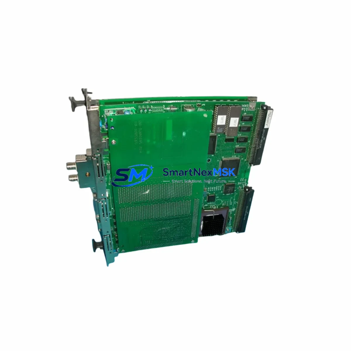
Yokogawa CP133E-32-S3 Retrofit-Ready CPU for STARDOM FCN/FCJ Control Systems
The Yokogawa CP133E-32-S3 is a high-reliability CPU module engineered for seamless retrofit and drop-in replacement within the STARDOM FCN and FCJ distributed control platforms. As legacy FCN/FCJ installations approach end-of-life or face discontinued spare-parts availability, the CP133E-32-S3 provides a verified upgrade path that preserves existing rack architecture, terminal wiring, and application logic — dramatically reducing the engineering effort and downtime risk associated with full system replacement.
This module is designed for industrial environments where control continuity is non-negotiable. Whether you are managing a refinery DCS migration, upgrading a water treatment SCADA node, or restoring a failed CPU in a remote FCJ cabinet, the CP133E-32-S3 delivers the processing headroom and communication flexibility required for modern automation demands. It supports the STARDOM FCN rack backplane interface natively, eliminating the need for adapter hardware or backplane rewiring during installation.
Before deploying the CP133E-32-S3 as a replacement, engineers should verify several critical compatibility parameters. Power supply capacity within the existing control cabinet must be confirmed — the FCN power supply module (such as the PW481 or PW482 series) must deliver sufficient rail voltage and current margin for the CP133E-32-S3’s operating envelope. Terminal block wiring on associated I/O modules, including analog input cards (AI141, AI143) and digital output cards (DO141, DO181), does not require modification, as the backplane signal routing remains consistent across the FCN CPU family.
Module address configuration is handled via the FCN engineering tool (FAST/TOOLS or ORB-based project environment). When replacing a failed CP133E-32-S3 or its predecessor, the module slot address and node ID must be re-entered to match the original project configuration. Technicians should export and archive the existing project file before any hardware swap to protect program logic, function block diagrams, and PID loop parameters.
HMI screen compatibility is a common concern during FCN/FCJ CPU upgrades. Existing FAST/TOOLS HMI faceplates and trend displays linked to the original CPU node will continue to function without modification, provided the replacement CP133E-32-S3 is assigned the same IP address and node name as the outgoing unit. Communication links — including Ethernet/IP, Modbus TCP, and OPC DA/UA connections to upstream SCADA or historian systems — should be validated post-swap using a loop-check procedure before returning the system to automatic control.
Upgrade Compatibility Table
| Parameter | Detail |
|---|---|
| Compatible Rack | STARDOM FCN / FCJ Backplane (standard slot) |
| Replaces | CP133, CP133E, CP133E-32-S1, CP133E-32-S2 and equivalent legacy CPUs |
| Backplane Interface | Native FCN backplane — no adapter required |
| Communication Ports | Dual Ethernet (100BASE-TX), RS-232C serial |
| Protocol Compatibility | Modbus TCP, OPC DA/UA, Ethernet/IP, FOUNDATION Fieldbus (via coupler) |
| Power Requirement | 5 VDC via backplane; confirm PW481/PW482 capacity ≥ rated load |
| Installation Requirement | Slot 0 (CPU slot); project re-download required after swap |
| HMI Compatibility | FAST/TOOLS R10.x and above; retain original node IP and name |
| Commissioning Note | Verify I/O module addresses and re-confirm PID parameters post-swap |
| Warranty | 12-Month Warranty — covered from date of shipment |
Retrofit Planning for Existing Automation Systems
A successful FCN/FCJ retrofit begins with a thorough site survey of the existing control cabinet. Identify all modules installed in the FCN rack: the CP133E-32-S3 CPU occupies Slot 0, while I/O modules such as the AI141 analog input, DI141 digital input, DO141 digital output, and AO141 analog output cards occupy downstream slots. The NP1L-RS4 or NP1L-ET1 communication modules, if present, handle serial and Ethernet gateway functions and should be inventoried separately, as their firmware versions may affect protocol handshake behavior with the replacement CPU.
The FCN rack itself — typically the NP1R-08 or NP1R-16 chassis — does not require replacement during a CPU swap, provided the backplane bus is undamaged. Inspect the backplane connector on the outgoing CPU for bent pins or corrosion before inserting the CP133E-32-S3. If the FCJ variant is in use (a compact, fanless controller), confirm that the CP133E-32-S3 is rated for the FCJ form factor, as FCJ and FCN share the same CPU module family but differ in rack depth and cooling requirements.
For sites running older STARDOM software environments, the programming cable (typically a standard Ethernet crossover or straight-through Cat5e cable connected to the CPU’s engineering port) is used to download the restored project file. Ensure the engineering workstation running FAST/TOOLS or the ORB configuration tool is on the same subnet as the CPU’s engineering IP address. After project download, perform a cold-start sequence and verify that all I/O modules — including any NP1L-RS4 serial communication modules linked to field instruments — report healthy status in the diagnostic view.
Downtime Control During System Migration
Minimizing unplanned downtime during a CP133E-32-S3 swap requires preparation before the maintenance window opens. The recommended sequence is: (1) export and verify the current project file from the running CPU using FAST/TOOLS; (2) pre-configure the replacement CP133E-32-S3 on a bench setup if possible, downloading the project and confirming module recognition offline; (3) schedule the physical swap during a planned shutdown or low-production window; (4) after insertion, download the project, perform a warm restart, and confirm all I/O modules and communication links are active before releasing control to automatic mode.
Where a hot-standby configuration is in place using a redundant CP133E-32-S3 pair, the switchover to the standby CPU can be initiated before removing the primary unit, ensuring zero interruption to field control outputs. For simplex (non-redundant) installations, the control loop outputs will be in their last-value or safe-state condition during the swap interval — typically under 15 minutes for a prepared technician. Analog output modules such as the AO141 should be confirmed in manual hold mode at the DCS console before the CPU is removed to prevent unintended valve or actuator movement.
After the CP133E-32-S3 is restored to service, validate communication continuity with upstream systems: confirm OPC DA/UA tag subscriptions are re-established with the historian, verify Modbus TCP polling from the SCADA host is receiving live data, and check that any FOUNDATION Fieldbus segments connected via coupler modules are reporting device health correctly. Document the swap date, firmware version of the replacement module, and any parameter adjustments made during commissioning for the site maintenance record.
Retrofit Support FAQ
Q: Is the CP133E-32-S3 a direct drop-in replacement for the CP133E-32-S1 and CP133E-32-S2?
A: Yes. The CP133E-32-S3 is backward-compatible with earlier S1 and S2 suffix variants within the STARDOM FCN/FCJ CPU family. The backplane connector, slot position, and project file format are identical. A project re-download is required after the swap; no hardware wiring changes are needed.
Q: What commissioning steps are required after installing the replacement CPU?
A: After physical installation, connect the engineering workstation via Ethernet to the CPU’s engineering port, download the archived project file using FAST/TOOLS or the ORB tool, perform a cold or warm start as appropriate, and verify all I/O module statuses in the diagnostic screen. Confirm PID loop setpoints, communication link health, and HMI tag connectivity before returning to automatic control.
Q: Will existing terminal wiring on I/O modules need to be changed?
A: No. Terminal wiring on field I/O modules (AI141, DI141, DO141, AO141, etc.) is connected to the I/O module terminals, not directly to the CPU. A CPU swap does not require any rewiring of field terminals. Only the CPU module itself is replaced in Slot 0 of the FCN rack.
Q: What does the 12-month warranty cover?
A: The 12-month warranty covers manufacturing defects and functional failures under normal operating conditions from the date of shipment. Each CP133E-32-S3 unit undergoes pre-shipment functional testing, including power-on self-test, backplane communication verification, and Ethernet port validation. Warranty claims are supported by our technical team at [email protected].
© 2026 SMARTNEXMSK. All rights reserved.
Original Source: https://smartnexmsk.com
Contact: [email protected] | +86 18259474341



