
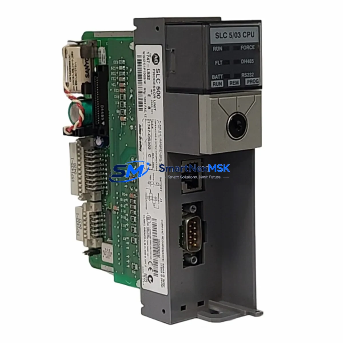
Allen-Bradley 1747-L532 Retrofit-Ready CPU for SLC 500 Control Systems
The Allen-Bradley 1747-L532 is a SLC 5/03 series CPU module designed for the SLC 500 modular chassis platform. With 16K words of user memory, onboard DH-485 and RS-232 communication ports, and full compatibility with the SLC 500 I/O backplane, this module is the preferred retrofit solution for facilities managing aging SLC 5/01 and SLC 5/02 installations that require expanded memory, improved diagnostics, or communication protocol upgrades without a full control system replacement.
For engineers and maintenance teams executing brownfield modernization projects, the 1747-L532 offers a cost-effective migration path. It installs directly into any standard 1746 series modular chassis — including the 1746-A4, 1746-A7, 1746-A10, and 1746-A13 — and is backward-compatible with existing 1746 series I/O modules such as digital input/output cards, analog modules, and specialty function modules already installed in the control cabinet.
Upgrade Compatibility Table
| Parameter | Details |
|---|---|
| Replaces / Upgrades From | 1747-L511 (SLC 5/01), 1747-L514 (SLC 5/01), 1747-L524 (SLC 5/02) |
| Compatible Chassis | 1746-A4, 1746-A7, 1746-A10, 1746-A13 |
| Communication Ports | DH-485 (Channel 0), RS-232 / DF1 (Channel 1) |
| User Memory | 16K Words |
| I/O Compatibility | All 1746 series digital, analog, and specialty I/O modules |
| Programming Software | RSLogix 500 / RSLogix Micro (ACD/RSS file format) |
| Programming Cable | 1747-CP3 (RS-232) or 1747-UIC USB-to-DH485 adapter |
| HMI Compatibility | PanelView 300, 550, 600, 900, 1000 via DH-485 or DF1 |
| Installation Requirement | Power-off chassis before swapping; verify 1746-P series PSU capacity |
| Retrofit Complexity | Low — direct slot replacement, no chassis modification required |
| Warranty | 12 Months — covers manufacturing defects and functional failure |
Retrofit Planning for Existing Automation Systems
A successful 1747-L532 retrofit begins well before the module arrives on-site. The first step is auditing the existing 1746 series chassis to confirm the installed 1746-P2 or 1746-P4 power supply has sufficient current capacity to support the SLC 5/03 CPU alongside all installed I/O modules. The SLC 5/03 draws slightly more backplane current than the SLC 5/01, and an undersized power supply is a common cause of intermittent faults after an otherwise clean swap.
Next, retrieve and back up the existing program from the original CPU using RSLogix 500 before removal. If the original CPU is a 1747-L511 or 1747-L524 and the programming cable is a legacy 1747-CP3 serial cable, ensure the engineering laptop has an active RS-232 port or a reliable USB-to-serial adapter. The 1747-UIC USB-to-DH485 interface cable is the recommended alternative for modern laptops and provides a stable connection for both program upload and online monitoring.
Terminal wiring on the 1746 series I/O modules — including 1746-IB16 digital input cards, 1746-OB16 digital output cards, and 1746-NI4 analog input modules — does not require modification during a CPU swap. All field wiring remains connected to the I/O terminal blocks throughout the procedure, which significantly reduces retrofit labor time and eliminates re-termination errors.
For systems using a PanelView 500 or PanelView 550 HMI connected via DH-485, the node address configuration on the 1747-L532 must match the original CPU’s DH-485 node number. This is set via the channel configuration in RSLogix 500 and should be verified before going online. If the HMI application references specific data file addresses — such as N7, B3, or F8 files — confirm that the program file structure is preserved identically in the uploaded .RSS file to avoid screen communication errors at startup.
In multi-rack SLC 500 systems using a 1747-SN Scanner Module for remote I/O expansion, the scanner configuration and rack addressing must be reviewed after the CPU replacement. The 1747-L532 supports the same remote I/O protocol as its predecessors, but scanner module parameters stored in the CPU data table must be re-verified if the program was modified during the migration. Similarly, if the system includes a 1747-KE or 1747-KFC15 communication module for third-party device integration, the DF1 port settings on Channel 1 of the new CPU must be reconfigured to match the original baud rate, parity, and station address settings.
Downtime Control During System Migration
Minimizing production downtime during a SLC 500 CPU replacement requires a structured pre-outage preparation protocol. Before scheduling the maintenance window, complete the following offline: upload and verify the existing program, document all I/O module addresses and channel configurations, photograph all terminal wiring and DIP switch settings, and prepare a tested spare 1747-L532 with the program pre-loaded and verified in RSLogix 500.
During the outage window, the physical swap of the 1747-L532 into the 1746 chassis takes under five minutes. The majority of commissioning time is spent on communication verification — confirming DH-485 node addressing, DF1 port parameters, and HMI data link integrity. With pre-loaded program files and documented configurations, most SLC 5/03 CPU replacements can be completed and returned to RUN mode within 30 to 60 minutes of planned downtime.
To protect original program logic, never overwrite the backup .RSS file during commissioning. Maintain a version-controlled archive of all program revisions, including pre-retrofit and post-retrofit builds. If the system uses a 1747-SCNR or 1747-SN remote I/O scanner, keep the scanner in IDLE mode until the CPU is confirmed online and all local I/O is responding correctly before enabling remote rack communication.
For critical production lines where even brief unplanned stops carry significant cost, consider staging a fully configured 1747-L532 as a hot spare. This approach — combined with a documented swap procedure and pre-tested program file — reduces mean time to repair (MTTR) to under 15 minutes in the event of an unplanned CPU failure.
Retrofit Support FAQ
Q1: Is the 1747-L532 a direct drop-in replacement for the 1747-L524 (SLC 5/02)?
Yes. The 1747-L532 installs into the same slot in any 1746 series modular chassis and is electrically and mechanically compatible. The program file (.RSS) created for the SLC 5/02 can be opened and downloaded directly to the SLC 5/03 using RSLogix 500 without modification. Verify that the power supply current budget accommodates the SLC 5/03 before installation.
Q2: What wiring changes are required when replacing the CPU?
No field wiring changes are required. All terminal connections remain on the 1746 series I/O modules, which stay in place during the CPU swap. Only the programming cable connection to Channel 1 (RS-232) or the DH-485 port (Channel 0) needs to be re-established after installation for program download and online verification.
Q3: How is compatibility with existing HMI screens verified after replacement?
After the 1747-L532 is installed and the program is downloaded, place the CPU in RUN mode and monitor the HMI communication status. For PanelView terminals connected via DH-485, confirm the node address matches the original CPU configuration. For DF1 connections on Channel 1, verify baud rate, parity, and stop bits in RSLogix 500 Channel Configuration. All data file references (N, B, F, T, C files) used by the HMI application must exist in the uploaded program file.
Q4: What does the 12-month warranty cover, and how is it claimed?
The 12-month warranty covers manufacturing defects and functional failure under normal operating conditions. It does not cover damage from incorrect installation, overvoltage, or physical mishandling. To initiate a warranty claim, contact SMARTNEXMSK with the order reference number and a description of the fault. Replacement or repair will be arranged within the warranty period. All units are function-tested prior to shipment.
© 2026 SMARTNEXMSK. All rights reserved.
Original Source: https://smartnexmsk.com
Contact: [email protected] | +86 18259474341



