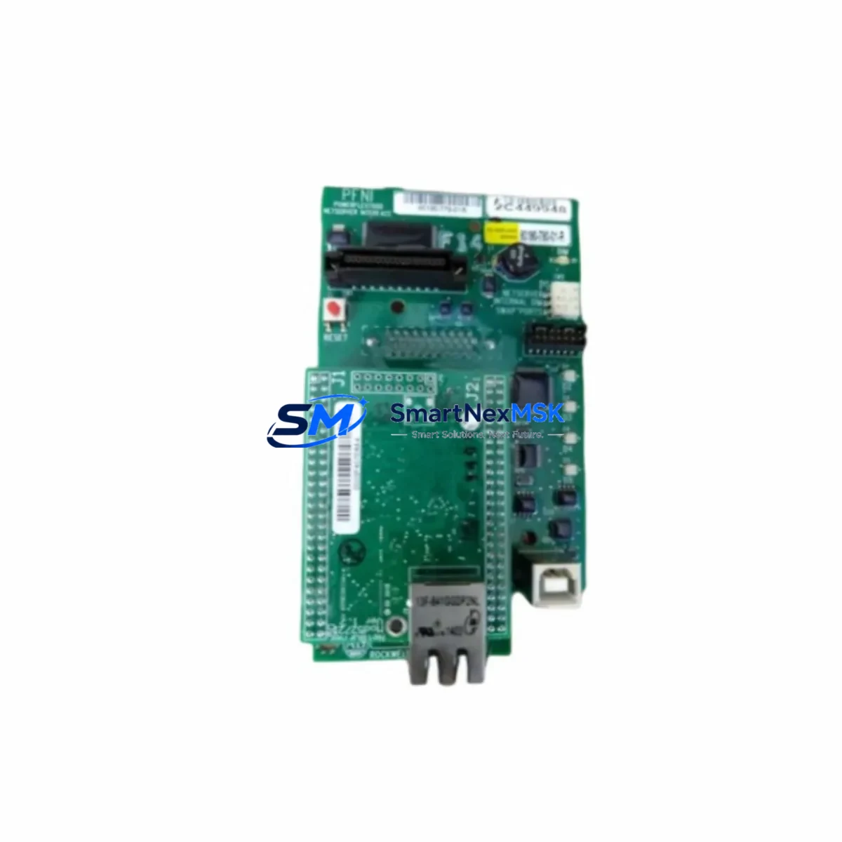
Allen-Bradley 1756-OF8H Retrofit-Ready Analog Output for ControlLogix Systems
The Allen-Bradley 1756-OF8H is an 8-channel, high-resolution analog output module designed for the ControlLogix 1756 platform. As legacy control systems age and original spare parts become increasingly difficult to source, the 1756-OF8H has emerged as a critical retrofit component for engineers managing aging production lines, upgrading distributed control architectures, and restoring discontinued automation equipment. Whether you are replacing a failed module in an existing 1756 chassis or planning a phased migration from an older PLC-5 or SLC 500 platform, the 1756-OF8H delivers the signal fidelity, backplane compatibility, and software integration required for a smooth, low-risk transition.
Each channel supports both voltage (±10V) and current (0–20mA / 4–20mA) output modes, configurable independently via Logix Designer (formerly RSLogix 5000). The module occupies a single slot in any 1756 series chassis — including the 1756-A4, 1756-A7, 1756-A10, 1756-A13, and 1756-A17 — and communicates over the ControlLogix backplane without requiring an additional communication adapter. This makes it directly interchangeable with earlier revisions of the same module family, and compatible with any 1756-L series controller, from the legacy 1756-L55 to the current 1756-L85E.
Upgrade Compatibility Table
| Parameter | Details |
|---|---|
| Module SKU | 1756-OF8H |
| Platform | Allen-Bradley ControlLogix 1756 Series |
| Channels | 8 Analog Output (Voltage / Current) |
| Output Range | ±10V DC / 0–20mA / 4–20mA (per channel) |
| Backplane Interface | ControlLogix 1756 backplane (single slot) |
| Compatible Chassis | 1756-A4, 1756-A7, 1756-A10, 1756-A13, 1756-A17 |
| Compatible Controllers | 1756-L55, 1756-L61, 1756-L63, 1756-L71, 1756-L73, 1756-L83E, 1756-L85E |
| Programming Software | Studio 5000 Logix Designer / RSLogix 5000 v16+ |
| Wiring Compatibility | Removable terminal block (RTB) — 1756-TBCH or 1756-TBS6H |
| Installation Requirement | Hot-swap capable; no chassis power-down required |
| Communication | ControlLogix backplane (no separate comm module needed) |
| Replacement Recommendation | Direct drop-in for all prior 1756-OF8H revisions (Rev A–D) |
| Commissioning Note | Verify module tag mapping and AO scaling in controller tag database before going live |
| Warranty | 12 Months — covers hardware defects, DOA replacement, and functional verification |
Retrofit Planning for Existing Automation Systems
Successful integration of the 1756-OF8H into a legacy or transitional control system requires careful pre-installation planning. Before removing the failed or obsolete module, engineers should document the existing terminal block wiring using the removable terminal block (RTB) — typically a 1756-TBCH or 1756-TBS6H — to ensure field wiring can be transferred without re-termination errors. Each channel’s output type (voltage or current) must be confirmed against the connected field device, whether that is a control valve positioner, variable frequency drive (VFD) reference input, or process transmitter setpoint.
When migrating from a PLC-5 or SLC 500 platform, the analog output addressing model changes significantly. PLC-5 systems use rack/slot/word addressing, while the ControlLogix platform uses tag-based addressing within Studio 5000. Engineers must remap all analog output tags in the controller program and verify that the HMI faceplate — whether running on a PanelView Plus 7, FactoryTalk View SE, or a third-party SCADA — correctly references the new tag structure. Failure to update HMI tag bindings is one of the most common causes of post-migration commissioning delays.
For systems using a 1756-EN2T or 1756-EN3TR EtherNet/IP communication module to connect the ControlLogix chassis to a plant-wide DCS or SCADA network, the 1756-OF8H module data is exposed automatically through the controller’s I/O tree and requires no additional configuration at the network layer. However, if the system uses a 1756-DNB DeviceNet bridge or a 1756-DHRIO Data Highway Plus remote I/O adapter for legacy field device connectivity, engineers should verify that the analog output module’s slot assignment does not conflict with existing remote I/O node addresses.
Power budget verification is essential before adding or replacing modules in a populated chassis. The 1756-OF8H draws power from the 1756 series backplane power supply — typically a 1756-PA75 or 1756-PB75 — and its current draw must be accounted for alongside other installed modules such as digital I/O modules (1756-IB16, 1756-OB16E), analog input modules (1756-IF8, 1756-IF16), and communication modules. Exceeding the chassis power budget will cause unpredictable module behavior and potential system faults.
For systems where the 1756-OF8H is being added as part of an I/O expansion — rather than a direct replacement — engineers should also confirm that the 1756-L series controller’s I/O tree has available slots and that the Logix Designer project file has been updated to include the new module definition before downloading the revised program to the controller.
Downtime Control During System Migration
Minimizing unplanned downtime is the primary operational concern during any analog output module replacement or system migration. The 1756-OF8H supports hot-swap installation, meaning the module can be removed and reinserted while the chassis remains powered, provided the controller is placed in Program mode first. This eliminates the need for a full system shutdown in most retrofit scenarios and allows field engineers to complete the physical swap within a planned maintenance window of 15–30 minutes.
Before initiating the swap, the controller program should be placed in Program mode and the current project file should be backed up from the controller using Studio 5000’s “Upload” function. This preserves the existing ladder logic, function block diagrams, and all analog scaling parameters — including engineering unit conversions, output clamping limits, and fault state configurations — so that the program can be restored immediately if the new module requires re-commissioning.
After physical installation, the module will appear in the I/O tree with an “Inhibited” or “Faulted” status until the controller recognizes it. Clearing the inhibit flag and transitioning the controller back to Run mode will restore analog output signals to field devices within seconds. Engineers should monitor the first 10–15 minutes of operation to confirm that all output channels are producing the correct signal levels and that no process alarms have been triggered by unexpected output transients during the transition.
For critical processes where even a brief interruption is unacceptable, a parallel commissioning approach is recommended: install the new 1756-OF8H in an adjacent chassis slot, configure it in the Logix Designer project as a secondary module, verify all output values in Program mode against expected setpoints, and then perform a controlled switchover during a scheduled process pause. This approach is particularly effective in continuous process industries such as chemical, oil and gas, and power generation, where analog output signals directly control flow control valves, burner management systems, or turbine governor inputs.
Retrofit Support FAQ
Q1: Is the 1756-OF8H a direct drop-in replacement for all previous revisions of the same module?
Yes. All hardware revisions of the 1756-OF8H (Rev A through Rev D) are backplane-compatible and use the same removable terminal block wiring interface. The module definition in Studio 5000 / RSLogix 5000 is identical across revisions, so no program changes are required when replacing an older revision with a newer one. Verify the firmware revision of the replacement module matches or exceeds the minimum required by your controller firmware version.
Q2: What wiring checks are required before installing the replacement module?
Remove the RTB (1756-TBCH or 1756-TBS6H) from the failed module and inspect each terminal for correct wire gauge, secure termination, and absence of corrosion or heat damage. Verify that the field wiring polarity matches the channel configuration (voltage vs. current) defined in the controller program. Re-seat the RTB onto the new module before sliding it into the chassis slot to avoid live-wiring errors.
Q3: How is the replacement module tested before shipment?
All 1756-OF8H units supplied by SMARTNEXMSK undergo functional verification testing prior to shipment. Each module is powered up, all 8 output channels are exercised across the full output range (voltage and current modes), and the backplane communication interface is verified. A test report is available upon request. All units are covered by a 12-month warranty from the date of shipment, covering hardware defects and DOA (dead-on-arrival) replacement at no additional cost.
Q4: Can the 1756-OF8H be used in a mixed-revision ControlLogix chassis alongside older modules?
Yes. The ControlLogix platform is designed for mixed-module operation. The 1756-OF8H can coexist in the same chassis with legacy analog input modules (1756-IF8), digital I/O modules (1756-IB16, 1756-OB16E), and communication modules (1756-EN2T, 1756-DHRIO) without compatibility issues, provided the chassis power budget is not exceeded. Always verify the total current draw of all installed modules against the rated output of the installed 1756-PA75 or 1756-PB75 power supply before finalizing the chassis configuration.
© 2026 SMARTNEXMSK. All rights reserved.
Original Source: https://smartnexmsk.com
Contact: [email protected] | +86 18259474341