
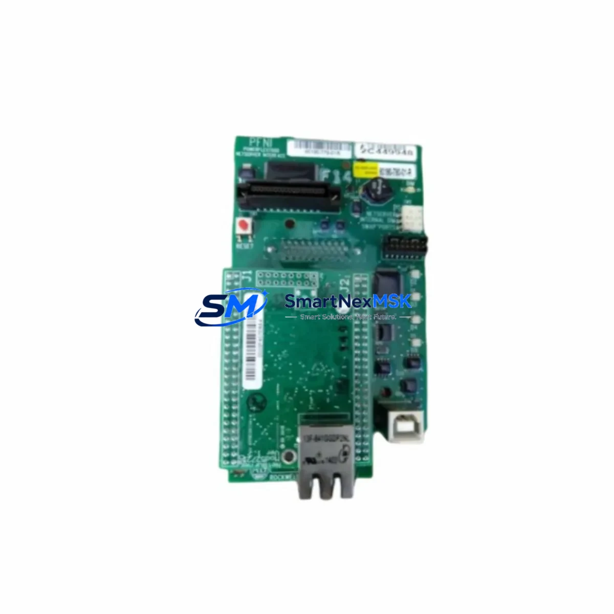
Allen-Bradley 80190-780-01-R Retrofit-Ready Drive Board for PowerFlex Control Systems
The Allen-Bradley 80190-780-01-R is a drive control board engineered for seamless compatibility with the PowerFlex family of AC variable frequency drives. As legacy PowerFlex 70, PowerFlex 700, and PowerFlex 40 installations reach end-of-service milestones, procurement teams and maintenance engineers increasingly rely on verified replacement boards like the 80190-780-01-R to restore drive functionality without committing to a full drive replacement. This board addresses the most common failure modes in PowerFlex drive platforms — including gate driver faults, control power loss, and communication dropouts — making it a critical stocking item for any facility running Allen-Bradley AC drive infrastructure.
Before installing the 80190-780-01-R, engineers should verify the existing drive’s DC bus voltage rating, confirm that the control power supply (typically 24 VDC internal or external) is within specification, and inspect the ribbon cable and terminal block connectors on the existing control board for corrosion or mechanical damage. The board interfaces directly with the PowerFlex drive’s main power board via a standardized backplane connector, and no firmware re-flashing is required in most standard configurations. However, if the drive’s parameter set has been customized — including PID tuning, speed reference scaling, or fault response logic — those parameters should be backed up via DriveExplorer or Studio 5000 Logix Designer before the swap to ensure program continuity after the board is seated.
In retrofit scenarios involving older PowerFlex 70 frames, technicians frequently encounter situations where the original 80190-780-01-R board is no longer available through standard distribution channels. In these cases, the replacement board must be cross-referenced against the drive’s catalog number and frame size to confirm pin-out compatibility. The 1336 PLUS II and 1305 series drives, while using different form factors, share similar control architecture philosophies, and engineers migrating from those platforms to PowerFlex will find the terminal wiring conventions largely consistent. For I/O expansion in modernized panels, the 1769-IQ16 and 1769-OB16 CompactLogix I/O modules are commonly integrated alongside the retrofitted drive to handle discrete signal routing that was previously managed by legacy relay logic.
Communication protocol migration is another key consideration during PowerFlex drive retrofits. Many older installations rely on RS-485 DH-485 or hardwired analog speed references. Upgrading to EtherNet/IP using a 20-COMM-E communication adapter mounted to the PowerFlex drive’s peripheral port allows the retrofitted drive to integrate directly into a Studio 5000 project, enabling Add-On Instructions (AOIs) for drive control and real-time diagnostics via FactoryTalk View SE HMI screens. If the existing HMI is a PanelView 550 or PanelView Plus 600, screen tag remapping will be required to align with the new drive’s parameter addresses after the 80190-780-01-R board is installed.
For control cabinet upgrades running on a 1756 ControlLogix or 1769 CompactLogix backplane, the 80190-780-01-R retrofit is typically paired with a review of the 1756-PA75 or 1756-PB75 power supply capacity to ensure the expanded I/O and communication modules do not exceed the chassis power budget. Rack-level planning should also account for any 1756-EN2T EtherNet/IP bridge modules used to segment the drive network from the controller backplane. Proper module addressing and slot assignment in the I/O tree must be confirmed before going live to prevent address conflicts that could trigger E-stop conditions during commissioning.
All 80190-780-01-R units supplied by SMARTNEXMSK are sourced from verified industrial supply channels, individually inspected prior to dispatch, and covered by a 12-month warranty against manufacturing defects and functional failure. Units are shipped from in-stock inventory with standard lead times of 3–7 business days for international destinations. Each board is packaged in anti-static ESD shielding with full traceability documentation available upon request.
Upgrade Compatibility Table
| Parameter | Details |
|---|---|
| Compatible Drive Series | PowerFlex 70, PowerFlex 700, PowerFlex 40 (verify frame size) |
| Backplane Interface | Standard PowerFlex control board connector; direct drop-in replacement |
| Control Power Input | 24 VDC (internal or external supply — confirm before installation) |
| Communication Compatibility | Native analog/digital I/O; EtherNet/IP via 20-COMM-E adapter |
| Installation Requirement | Parameter backup recommended; no firmware flash required in standard config |
| Replacement Recommendation | Direct replacement for failed or end-of-life 80190-780-01-R boards |
| Commissioning Notes | Verify PID parameters, speed reference scaling, and fault response logic post-swap |
| Warranty | 12 months — covers manufacturing defects and functional failure |
Retrofit Planning for Existing Automation Systems
A successful PowerFlex drive retrofit using the 80190-780-01-R begins well before the board arrives on-site. Maintenance teams should compile a full bill of materials for the control cabinet, including the existing 1756-L71 or 1769-L33ER controller, the 1756-EN2T communication bridge, any 1769-IQ16 or 1769-OB16 I/O modules, and the 1756-PA75 chassis power supply. Verifying that the backplane has sufficient power headroom for the retrofitted drive’s control board is essential — an undersized 1756-PB75 power supply is a common root cause of intermittent faults after board replacement.
Terminal wiring should be documented with photographs before disconnecting any conductors. The 80190-780-01-R uses the same terminal block layout as the original board, but wire labeling on older installations is frequently inconsistent. Confirm the analog speed reference input (typically terminals 1–3 on the control terminal strip), the digital enable input, and the fault relay output wiring before powering up. If the drive is connected to a 20-COMM-E EtherNet/IP adapter, the adapter’s IP address and node configuration should be recorded and re-applied after the board swap. For installations using a 1203-USB or 1203-SSS programming cable for local parameter access, confirm cable driver compatibility with the engineering workstation’s operating system before the maintenance window begins.
HMI screen validation is a frequently overlooked step in drive retrofits. PanelView Plus 700 and PanelView Plus 1000 displays connected via EtherNet/IP should be tested for tag connectivity after the 80190-780-01-R is installed and the drive is powered. Any FactoryTalk View ME application referencing drive-specific parameters should be verified against the restored parameter set to confirm that speed feedback, current display, and fault status tags are reading correctly before the system is returned to production.
Downtime Control During System Migration
Minimizing unplanned downtime during a PowerFlex drive board replacement requires a structured pre-outage checklist. Before the maintenance window, back up all drive parameters using DriveExplorer or the Studio 5000 drive configuration tool and store the file on a network share accessible from the plant floor. Confirm that a spare 80190-780-01-R is on-hand and has been visually inspected. Coordinate with the process control team to identify a safe window for drive isolation — typically during a scheduled production break or shift changeover.
During the swap, follow lockout/tagout (LOTO) procedures for the drive’s input disconnect. Allow the DC bus to fully discharge (minimum 5 minutes after power removal, or until the bus voltage indicator LED extinguishes) before touching any internal components. Seat the 80190-780-01-R firmly into the backplane connector and verify that all ribbon cables are fully engaged. On power-up, monitor the drive’s keypad display for fault codes — F005 (overcurrent) or F007 (motor overload) on initial startup typically indicate a parameter mismatch rather than a board fault, and can be resolved by restoring the backed-up parameter file.
Once the drive is running under no-load conditions, perform a controlled ramp test at 10%, 50%, and 100% speed reference to confirm that the output frequency, current draw, and speed feedback are within expected ranges. Document the commissioning results and update the plant’s maintenance management system (CMMS) with the board replacement record, including the new board’s serial number and installation date, to support the 12-month warranty claim process if required.
Retrofit Support FAQ
Q: Is the 80190-780-01-R a direct drop-in replacement for the original board in my PowerFlex 70 drive?
A: Yes, in the vast majority of PowerFlex 70 and PowerFlex 700 applications, the 80190-780-01-R is a direct replacement. Confirm your drive’s catalog number and frame size against the board’s compatibility data before installation. No firmware modification is required for standard configurations.
Q: Do I need to re-enter all drive parameters after replacing the control board?
A: If you backed up the parameter file using DriveExplorer or Studio 5000 prior to the swap, parameters can be restored in minutes. If no backup exists, the drive will default to factory settings and parameters will need to be re-entered manually — a process that typically takes 30–90 minutes depending on the complexity of the application.
Q: What commissioning checks should I perform after installing the 80190-780-01-R?
A: Verify control power voltage, confirm terminal wiring integrity, check communication adapter connectivity (if applicable), perform a no-load ramp test, and validate HMI tag readings. Review the drive’s fault log after the first full-load run to confirm no latent faults are present.
Q: What does the 12-month warranty cover, and how do I make a claim?
A: The 12-month warranty covers manufacturing defects and functional failure under normal operating conditions. To initiate a claim, contact SMARTNEXMSK at [email protected] with your order number, installation date, and a description of the fault. Replacement or repair will be arranged within 5 business days of claim verification.
© 2026 SMARTNEXMSK. All rights reserved.
Original Source: https://smartnexmsk.com
Contact: [email protected] | +86 18259474341



