
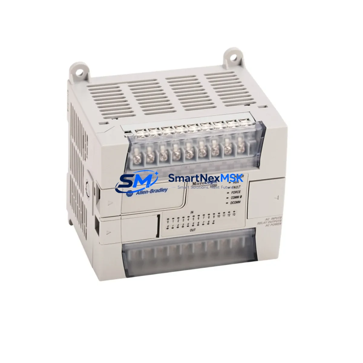
Allen-Bradley 1762-L24BWA Maintenance-Ready Spare for MicroLogix 1200 Automation
The Allen-Bradley 1762-L24BWA is a 24 I/O MicroLogix 1200 series programmable logic controller featuring relay output and AC power supply input. As a maintenance-ready original spare, this unit is sourced, inspected, and tested to support rapid field replacement in manufacturing lines, packaging systems, water treatment facilities, and general industrial automation environments. Holding a verified stock of the 1762-L24BWA directly reduces unplanned downtime risk — a critical factor for maintenance engineers managing aging MicroLogix 1200 control architectures.
For procurement and maintenance teams, the 1762-L24BWA represents a proven, long-lifecycle controller that remains widely deployed across global industrial sites. Its relay output configuration makes it suitable for direct load switching without additional output modules in many standard applications. When sourcing a replacement unit, confirming firmware revision compatibility and I/O mapping against the existing program is essential before commissioning.
Spare Maintenance Table
| Parameter | Specification |
|---|---|
| SKU / Part Number | 1762-L24BWA |
| Series | MicroLogix 1200 |
| Brand | Allen-Bradley (Rockwell Automation) |
| I/O Count | 24 (14 DI / 10 DO) |
| Output Type | Relay (Form A) |
| Power Supply | AC 100–240 V |
| Communication Port | RS-232 (Channel 0), RS-232/485 (Channel 1) |
| Programming Software | RSLogix 500 / Studio 5000 Logix Designer (legacy) |
| Operating Temperature | 0 °C to 60 °C |
| Mounting | DIN Rail or Panel Mount |
| Compatibility | MicroLogix 1200 expansion modules (1762 series) |
| Application Environment | Industrial automation, discrete manufacturing, utilities |
| Condition | Original / New Surplus / Tested |
| Warranty | 12 Months |
| Origin | USA |
Maintenance Planning for Continuous Operation
When scheduling a planned replacement or responding to an unplanned failure of the 1762-L24BWA, a thorough control cabinet inspection is strongly recommended. Maintenance engineers should treat the controller swap as an opportunity to audit the surrounding electrical environment to prevent repeat failures and extend system service life.
Begin with the power supply module feeding the controller — verify output voltage stability and check for capacitor aging or thermal stress marks. The 1762-OW8 relay output expansion module, commonly paired with the L24BWA in extended I/O configurations, should be inspected for contact wear and coil resistance. If the system uses analog signals, the 1762-IF4 analog input module warrants calibration verification to ensure signal accuracy post-replacement.
Communication integrity is equally critical. The RS-232 and RS-485 ports on the 1762-L24BWA connect to HMI panels — often a PanelView 300 or PanelView 550 — and to upstream SCADA or DCS nodes. Inspect communication cables, terminal connectors, and shielding continuity. A degraded 1761-CBL-PM02 programming cable or loose DB9 connector can cause intermittent communication faults that are misdiagnosed as controller failures.
Terminal blocks and wiring within the control cabinet should be checked for loose connections, insulation degradation, and corrosion — particularly on the relay output terminals where inductive load switching accelerates contact wear. Phoenix Contact or Weidmüller terminal blocks used in the same cabinet should be torqued to specification. Inline fuses protecting the relay output circuits should be replaced as a precautionary measure during any major controller swap.
For systems with signal isolation requirements, signal isolators or barriers on analog input channels should be tested for drift. If the installation includes a 1762-IQ16 digital input expansion module, verify input threshold voltages against field sensor outputs. Documenting the I/O address mapping and tag database before removing the old controller is essential to avoid commissioning errors on the replacement unit.
Finally, update the spare parts inventory record to reflect the consumed unit and initiate a replenishment order. Maintaining at least one additional 1762-L24BWA in stock — alongside critical expansion modules and communication cables — is a best practice for sites where MicroLogix 1200 systems remain in active production service.
Site Replacement Workflow
Step 1 — Pre-Replacement Preparation: Back up the existing program using RSLogix 500. Record all I/O wiring labels, communication port settings (baud rate, parity, node address), and any active data file values. Photograph the wiring before disconnection.
Step 2 — Safe Isolation: De-energize the control panel following LOTO (Lockout/Tagout) procedures. Confirm zero-energy state with a calibrated voltage tester before touching any terminals.
Step 3 — Module Removal: Disconnect all I/O wiring and communication cables. Remove the 1762-L24BWA from the DIN rail or panel mount. Note the firmware version label on the unit for compatibility reference.
Step 4 — Replacement Unit Verification: Confirm the replacement 1762-L24BWA firmware revision is compatible with the existing program. If necessary, update firmware via RSLogix 500 before installation. Verify relay output contact ratings match the load requirements.
Step 5 — Installation and Wiring: Mount the replacement unit, reconnect all I/O wiring per the documented labels, and restore communication cables. Torque all terminal screws to specification.
Step 6 — Program Download and Commissioning: Download the backed-up program. Verify all I/O points in run mode before resuming production. Test communication with connected HMI and any upstream systems. Document the replacement date and unit serial number in the maintenance log.
This structured workflow minimizes commissioning risk and ensures the replacement 1762-L24BWA is fully validated before returning the system to service — typically achievable within a single maintenance window.
Spare Parts Support FAQ
Q1: Is the 1762-L24BWA still available as a new or new-surplus unit?
A: Yes. While Rockwell Automation has transitioned focus to newer platforms, the 1762-L24BWA remains available as original new-surplus stock. Each unit shipped by SMARTNEXMSK is individually tested and verified before dispatch, with a 12-month warranty covering functional defects.
Q2: How do I confirm compatibility with my existing MicroLogix 1200 program?
A: Compatibility is determined by the firmware revision of the replacement unit relative to your program file. Use RSLogix 500 to check the firmware revision requirement in your .RSS file. Contact our technical team with your program version and we will confirm the appropriate firmware revision before shipment.
Q3: What is included in the 12-month warranty and what does the pre-shipment test cover?
A: Every 1762-L24BWA undergoes power-on functional testing, I/O point verification, and communication port check prior to shipment. The 12-month warranty covers all functional failures under normal operating conditions. Physical damage caused by incorrect installation or overvoltage is excluded.
Q4: Can I maintain a long-term supply agreement for the 1762-L24BWA and related MicroLogix 1200 components?
A: Yes. SMARTNEXMSK supports long-term supply agreements for industrial spare parts, including the 1762-L24BWA and associated expansion modules. Contact our sales team to discuss volume pricing, reserved stock arrangements, and scheduled delivery programs tailored to your maintenance cycle.
© 2026 SMARTNEXMSK. All rights reserved.
Original Source: https://smartnexmsk.com
Contact: [email protected] | +86 18259474341



