
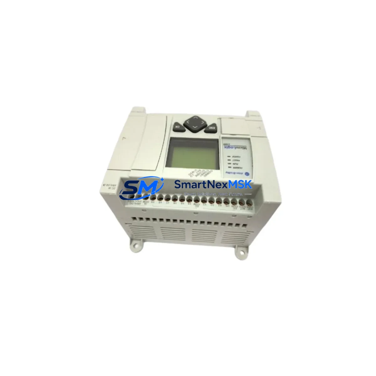
Allen-Bradley 1763-L16BBB Retrofit-Ready Controller for MicroLogix 1100: Compatible Modernization and Smooth System Upgrade
The Allen-Bradley 1763-L16BBB is a 16-point base unit belonging to the MicroLogix 1100 series, designed as a compact, relay-output programmable logic controller for small-to-mid-scale industrial automation. As legacy MicroLogix 1000 and MicroLogix 1200 installations reach end-of-life, the 1763-L16BBB has become the preferred retrofit-ready replacement for engineers managing aging control panels, discontinued spare parts, and production lines that cannot afford extended downtime.
This unit features 10 DC inputs and 6 relay outputs, an embedded EtherNet/IP port for network connectivity, and an RS-232/RS-485 combined serial port (Channel 0) for legacy device communication. It supports ladder logic programming via RSLogix 500 or Studio 5000 Logix Designer in compatibility mode, making it straightforward to migrate existing programs from older MicroLogix 1000 (1761-L16BWA, 1761-L32BWA) or MicroLogix 1200 (1762-L24BWA, 1762-L40BWA) platforms without full rewrite.
SMARTNEXMSK maintains verified stock of the 1763-L16BBB with full functional testing, 12-month warranty coverage, and same-week dispatch for urgent retrofit projects.
Upgrade Compatibility Table
| Parameter | 1763-L16BBB (This Unit) | Typical Legacy Unit | Notes |
|---|---|---|---|
| I/O Points | 10 DI / 6 Relay DO | Varies (8–24 pts) | Verify I/O count before swap |
| Communication Port | EtherNet/IP + RS-232/485 | RS-232 only (MicroLogix 1000) | EtherNet/IP enables SCADA integration |
| Power Supply | 24V DC input | 24V DC / 120V AC (model-dependent) | Confirm panel power rail before wiring |
| Backplane / Expansion | 1762 I/O expansion modules | 1762 series compatible | 1762-IQ16, 1762-OW16 directly compatible |
| Programming Software | RSLogix 500 v8.0+ | RSLogix 500 (all versions) | Program import supported; verify instruction set |
| Module Address | Slot 0 (base unit) | Slot 0 | Expansion modules addressed from Slot 1 |
| HMI Compatibility | PanelView Component, PanelView Plus | PanelView 550 / 600 | Update HMI tags after migration |
| Installation Format | DIN rail / panel mount | DIN rail / panel mount | Same footprint as 1762-series base |
| Warranty | 12 Months | N/A (discontinued) | Covered by SMARTNEXMSK warranty policy |
| Replacement Recommendation | Direct drop-in for MicroLogix 1000/1200 | — | Confirm terminal block wiring map |
Retrofit Planning for Existing Automation Systems
Successful retrofit of a MicroLogix 1100 1763-L16BBB into an existing control cabinet begins with a thorough audit of the current system architecture. Engineers should document the existing terminal block wiring layout, noting each input signal source and output load type — particularly whether relay outputs are driving AC or DC loads, as the 1763-L16BBB relay contacts are rated for both but require correct fusing per circuit.
If the legacy system uses a 1761-L16BWA (MicroLogix 1000) with a 1761-CBL-PM02 programming cable, the transition to the 1763-L16BBB requires switching to a 1761-CBL-HM02 or USB-to-serial adapter for Channel 0 access, or alternatively using the built-in EtherNet/IP port with a standard RJ-45 patch cable for direct laptop programming — a significant workflow improvement for field engineers.
For systems that include 1762-series expansion modules such as the 1762-IQ16 (16-point DC input), 1762-OW16 (16-point relay output), or 1762-IF4 (4-channel analog input), these modules connect directly to the 1763-L16BBB expansion port without modification. The 1762-OA8 (8-point 120V AC output) and 1762-OB16 (16-point DC output) modules are equally compatible, allowing engineers to preserve existing I/O infrastructure while upgrading only the base controller.
Power supply sizing is a critical checkpoint. The 1763-L16BBB draws approximately 350 mA at 24V DC from the system power supply. If the existing panel uses a 1606-XLP power supply or equivalent 24V DIN-rail unit, verify that the remaining current budget accommodates the controller plus all connected expansion modules and field devices. A 1606-XLP30E (30W, 24V DC) is typically sufficient for a 1763-L16BBB with two to three 1762-series expansion modules.
Communication migration is another key consideration. Legacy systems communicating via DF1 protocol over RS-232 to a SCADA host or a 1784-U2DHP USB-to-DH+ adapter can be preserved through Channel 0 on the 1763-L16BBB. However, the embedded EtherNet/IP port opens the path to Modbus TCP or EtherNet/IP messaging with modern SCADA platforms, Ignition SCADA, or FactoryTalk View SE without additional communication modules. For systems using a 1761-NET-ENI Ethernet interface on the legacy controller, this external adapter becomes redundant and can be removed, simplifying the panel layout.
HMI screen updates are often overlooked during retrofit planning. If the existing panel uses a PanelView Component C400 or C600 connected via RS-232, the tag database must be re-mapped to match the 1763-L16BBB’s data file structure. For PanelView Plus 600 or 700 terminals communicating over EtherNet/IP, the migration is more straightforward — update the controller IP address in the HMI project and verify all tag paths resolve correctly before going live.
Downtime Control During System Migration
Minimizing production downtime during a MicroLogix 1100 retrofit requires a structured pre-migration checklist executed before the scheduled maintenance window. The recommended approach is to upload and archive the existing program from the legacy controller using RSLogix 500, then perform a full offline simulation of the migrated program on the 1763-L16BBB using the RSLogix 500 emulator. This validates all rung logic, timer presets, counter values, and data file references before any physical swap occurs.
During the physical changeover, label all terminal block wires before disconnection. The 1763-L16BBB uses the same screw-terminal wiring convention as the 1762-series base units, so a pre-labeled wiring diagram significantly reduces reconnection time. Power down the panel, swap the controller, reconnect terminals in sequence, and restore power. Initial power-up should be performed in Program mode — never Run mode — to allow a final program verification before enabling outputs.
For systems where continuous control is critical, consider a parallel run strategy: install the 1763-L16BBB alongside the legacy controller on a temporary DIN rail, wire a subset of inputs in parallel, and validate output logic against the live system before the final cutover. This approach is particularly effective for conveyor control, pump sequencing, and temperature regulation loops where unexpected output state changes carry safety or quality risks.
After cutover, verify all communication links — EtherNet/IP connections to SCADA, serial links to drives or HMI panels, and any peer-to-peer MSG instructions to other controllers such as a CompactLogix L16ER or a MicroLogix 1400 (1766-L32BWA) on the same network. Confirm that all analog input scaling in the 1762-IF4 or 1762-IF2OF2 modules reads correctly against known process values before releasing the system to production.
Retrofit Support FAQ
Q1: Is the 1763-L16BBB a direct replacement for the MicroLogix 1000 1761-L16BWA?
A: Yes, with minor adjustments. The 1763-L16BBB is pin-compatible at the terminal block level for standard 24V DC input wiring. The primary differences are the addition of the EtherNet/IP port and the expanded instruction set. Existing RSLogix 500 programs written for the 1761-L16BWA can be imported and run on the 1763-L16BBB after verifying that no unsupported instructions are present. Review the program’s I/O configuration file to confirm input/output addresses map correctly to the new base unit.
Q2: What commissioning steps are required after installing the 1763-L16BBB?
A: After physical installation and wiring, assign a static IP address via BOOTP/DHCP or the controller’s built-in web server. Download the verified program in Program mode, force-test each I/O point against the field device, confirm all communication links are active, then switch to Run mode. Document the final IP address, node number, and program version in the panel’s maintenance log.
Q3: Can the 1763-L16BBB work with existing 1762-series expansion modules already installed in the panel?
A: Yes. The 1763-L16BBB is fully compatible with all 1762-series I/O expansion modules, including the 1762-IQ16, 1762-OW16, 1762-OB16, 1762-OA8, 1762-IF4, and 1762-IF2OF2. No hardware adapters are required. Expansion modules are addressed automatically starting at Slot 1 in the RSLogix 500 I/O configuration.
Q4: What does the 12-month warranty cover, and how is it handled?
A: SMARTNEXMSK’s 12-month warranty covers manufacturing defects and functional failures under normal operating conditions. Each unit undergoes pre-shipment functional testing including I/O point verification, communication port check, and power-on self-test. In the event of a warranty claim, contact [email protected] with the order reference and fault description. Replacement or repair is processed within the warranty period at no additional cost.
© 2026 SMARTNEXMSK. All rights reserved.
Original Source: https://smartnexmsk.com
Contact: [email protected] | +86 18259474341



