
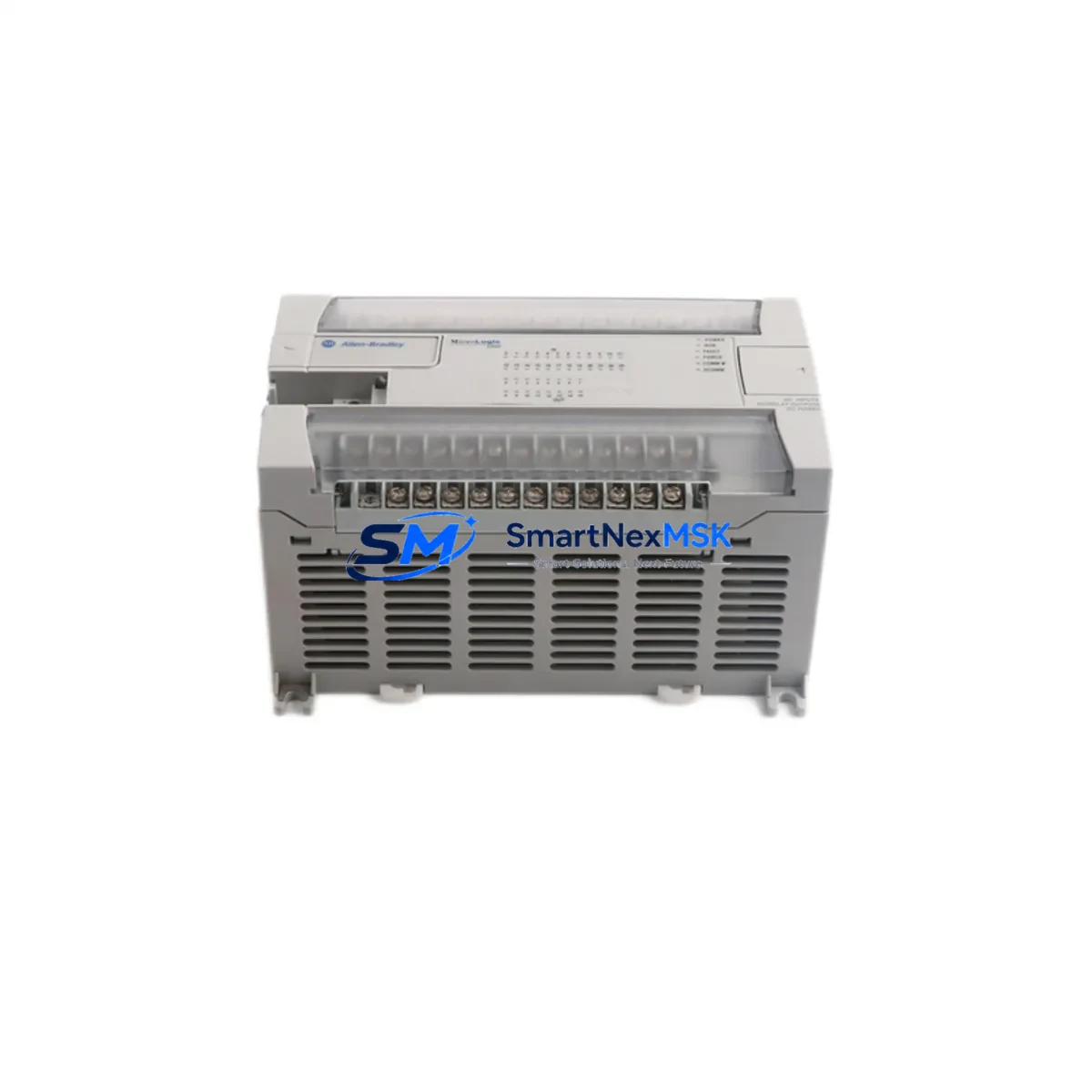
Allen-Bradley 1766-L32AWA Retrofit-Ready PLC for MicroLogix 1400 Control Systems
The Allen-Bradley 1766-L32AWA is a 32-point AC-powered relay output PLC controller from Rockwell Automation’s MicroLogix 1400 series, purpose-built for industrial control environments that demand reliable, drop-in compatibility with legacy automation infrastructure. Whether you are replacing a failed unit on an active production line, upgrading an aging control cabinet, or migrating from an earlier MicroLogix 1000 or MicroLogix 1100 platform, the 1766-L32AWA delivers the I/O density, communication flexibility, and programming continuity that retrofit engineers depend on.
This unit supports 20 digital inputs and 12 relay outputs, powered directly from 100–240V AC supply. Its onboard RS-232 and RS-485 communication ports enable seamless integration with existing HMI panels, SCADA systems, and remote I/O networks without requiring protocol converters or additional communication modules. The embedded EtherNet/IP port (via the 1766-MM1 memory module slot) further extends connectivity options for facilities transitioning toward Ethernet-based control architectures.
Upgrade Compatibility Table
| Parameter | 1766-L32AWA (This Unit) | Retrofit Notes |
|---|---|---|
| Power Supply | 100–240V AC | Direct replacement for AC-powered MicroLogix 1400 variants; verify panel supply voltage before installation |
| Digital I/O | 20 DI / 12 DO (Relay) | Pin-compatible with 1766-L32BWA and 1766-L32BWAA wiring harnesses in most installations |
| Communication Ports | RS-232 (Ch0), RS-485 (Ch1) | Retains existing DF1, DH-485, Modbus RTU, and ASCII protocol configurations |
| EtherNet/IP | Via 1766-MM1 module slot | Compatible with 1766-L32AWAA variant; confirm memory module presence |
| Backplane / Rack | Standalone (no rack required) | Mounts on standard DIN rail; no 1746 SLC rack needed |
| Programming Software | RSLogix 500 / Studio 5000 Logix Designer (import) | Existing .RSS program files upload directly; verify firmware revision compatibility |
| HMI Compatibility | PanelView 300, 550, 600, 800 series | DF1 and DH-485 driver tags remain valid; update communication path in HMI project if IP changes |
| Replacement Path | MicroLogix 1000, 1100, 1200 → 1400 | I/O mapping review required; ladder logic is largely portable with minor address remapping |
| Warranty | 12 Months | Covers manufacturing defects; includes pre-shipment functional test report |
Retrofit Planning for Existing Automation Systems
Successful retrofit of the 1766-L32AWA into an existing control system begins well before the unit arrives on site. Engineers should start by auditing the current control cabinet layout, documenting terminal block assignments, and photographing all existing wiring before disconnecting the legacy controller. In most MicroLogix 1400 installations, the 1766-L32AWA shares the same physical footprint and DIN rail mounting pattern, which eliminates the need for panel modifications.
Power supply verification is a critical first step. Confirm that the existing 24V DC auxiliary supply — typically sourced from a 1606-XLP or similar Rockwell power supply module — can support the 1766-L32AWA’s inrush current during startup. If the cabinet also houses a 1769-PA2 or 1769-PB2 CompactLogix power supply for expansion I/O, ensure that the combined load remains within rated capacity.
For systems using 1762-IQ8 or 1762-OW8 MicroLogix 1200 expansion modules, note that the 1766-L32AWA supports the 1762 I/O expansion bus directly, allowing existing expansion modules to be reused without rewiring. This is particularly valuable in installations where the 1762-IF4 analog input module or 1762-OF4 analog output module handles process variable signals from field transmitters.
Communication wiring should be preserved wherever possible. The 1761-CBL-PM02 or 1761-CBL-HM02 programming cables used with earlier MicroLogix platforms remain compatible with the 1766-L32AWA’s Channel 0 RS-232 port. If the existing network uses a 1761-NET-AIC Advanced Interface Converter for DH-485 multi-drop communication, the 1766-L32AWA integrates without modification.
Before powering up the replacement unit, upload the existing program from the failed controller if possible, or restore from the most recent RSLogix 500 backup file. Verify that all module addresses, I/O forcing states, and data file configurations match the original program. Pay particular attention to integer files (N7), timer files (T4), and counter files (C5) that may store accumulated process values critical to production continuity.
HMI screen updates are often overlooked during retrofit planning. If the facility uses a PanelView 550 or PanelView 600 terminal communicating via DF1 full-duplex on Channel 0, confirm that the node address and baud rate settings in the HMI project match the 1766-L32AWA configuration. No screen redesign is typically required, but a full functional test of all HMI screens against live I/O is recommended before returning the line to production.
Downtime Control During System Migration
Minimizing unplanned downtime during a MicroLogix 1400 replacement requires a structured pre-commissioning approach. Begin by preparing a complete I/O checkout checklist that maps every physical terminal to its corresponding ladder rung and data file address. This document becomes the commissioning script during the live cutover.
Where production schedules permit, perform a bench test of the 1766-L32AWA before installation. Load the production program, simulate input signals using a 1747-PIC or USB-1761-CBL-PM02 programming cable, and verify that all output logic executes correctly. This step catches firmware incompatibilities and program errors before the unit reaches the panel.
During the physical swap, label all terminal connections before removal and use the existing wiring documentation to restore connections in sequence. Power up the replacement unit with outputs disabled, verify all input states against the process, then enable outputs one group at a time while monitoring field devices. This staged approach protects actuators, drives, and downstream equipment from unexpected energization.
For facilities with redundant control paths or bypass circuits, coordinate the cutover with operations to ensure that manual overrides are in place for critical process loops. Document the exact time of cutover, the firmware version loaded, and the program checksum for maintenance records. A 12-month warranty covers the unit against manufacturing defects from the date of shipment, providing assurance during the post-commissioning observation period.
Retrofit Support FAQ
Q: Is the 1766-L32AWA a direct drop-in replacement for the 1766-L32BWAA?
A: The 1766-L32AWA (AC power, relay output) and 1766-L32BWAA (AC power, relay output with embedded EtherNet/IP) share the same I/O configuration and terminal layout. The primary difference is the onboard Ethernet port on the BWAA variant. If your application does not require EtherNet/IP, the L32AWA is a functionally equivalent replacement. If Ethernet connectivity is needed, a 1761-NET-ENI module can be added externally.
Q: Can I reuse my existing RSLogix 500 program without modification?
A: In most cases, yes. Programs developed for MicroLogix 1400 controllers upload directly to the 1766-L32AWA using RSLogix 500 v8.0 or later. Verify that the firmware revision on the replacement unit is equal to or higher than the original. If migrating from a MicroLogix 1200 (1762-Lxx series), an I/O address remapping step is required due to differences in the I/O configuration structure.
Q: What pre-shipment testing is performed on this unit?
A: Each 1766-L32AWA undergoes a functional power-on test, I/O continuity verification, and communication port check prior to shipment. A test report is available upon request. The unit ships with a 12-month warranty covering manufacturing defects from the date of delivery.
Q: How do I verify wiring compatibility before installation?
A: Download the 1766-L32AWA installation instructions (publication 1766-IN001) from the Rockwell Automation literature library and compare terminal designations against your existing wiring diagram. Pay particular attention to the input common (COM) groupings and relay output contact ratings, as these differ between AC and DC variants of the MicroLogix 1400 family.
© 2026 SMARTNEXMSK. All rights reserved.
Original Source: https://smartnexmsk.com
Contact: [email protected] | +86 18259474341



