
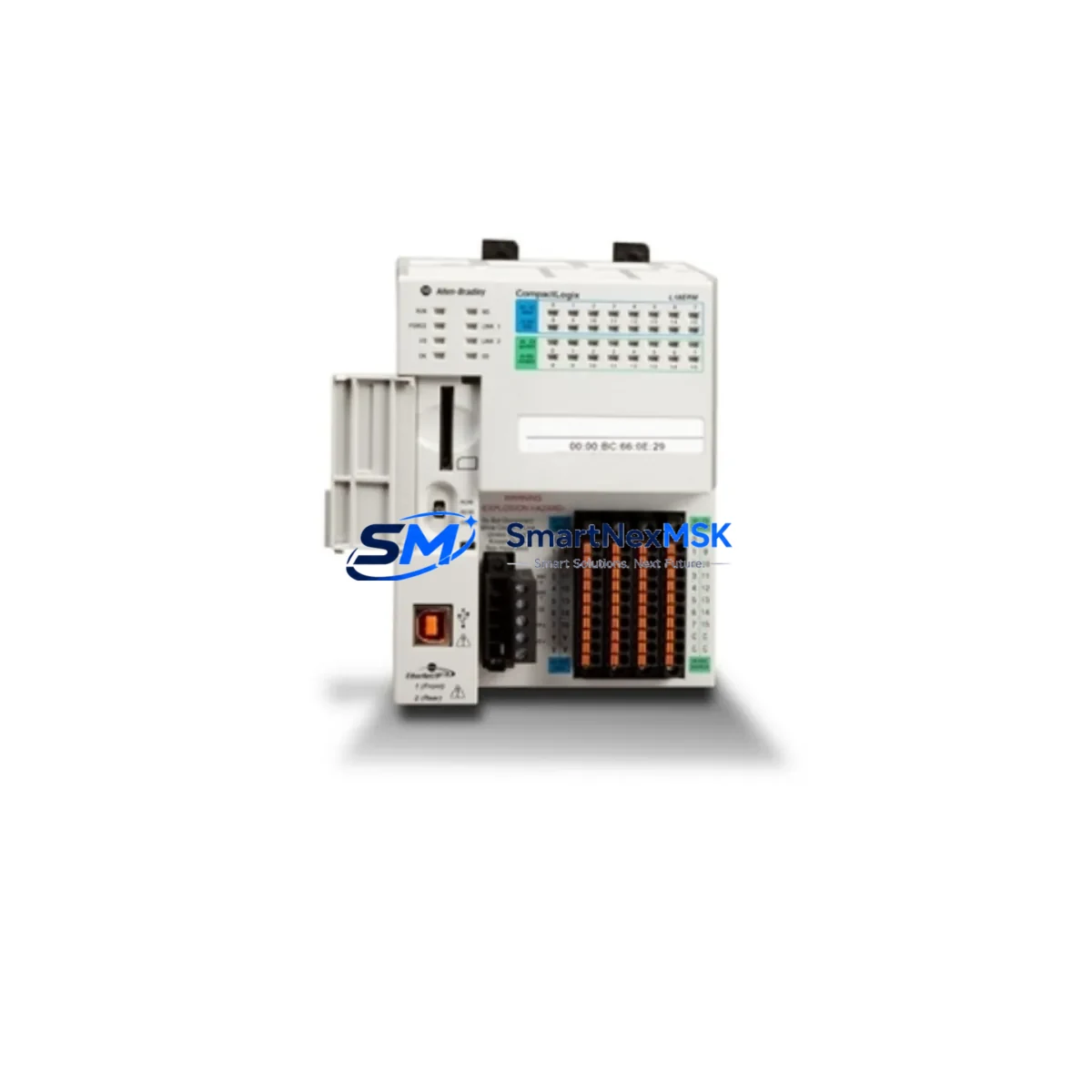
Allen-Bradley 1769-L18ER-BB1B Retrofit-Ready Controller for CompactLogix L1 Control Systems
The Allen-Bradley 1769-L18ER-BB1B is a CompactLogix 5370 L1 programmable logic controller engineered for seamless integration into legacy and modern control architectures. With 16 onboard digital I/O points, dual EtherNet/IP ports, and native compatibility with the Studio 5000 Logix Designer programming environment, this controller is the preferred retrofit solution for facilities migrating away from discontinued SLC 500, MicroLogix 1100, MicroLogix 1400, and early CompactLogix L20 platforms. Whether you are upgrading a standalone machine cell, modernizing a distributed control cabinet, or restoring a production line after an unplanned failure, the 1769-L18ER-BB1B delivers the processing power, communication flexibility, and I/O density required for a controlled, low-risk transition.
Upgrade Compatibility Table
| Parameter | Details |
|---|---|
| SKU / Part Number | 1769-L18ER-BB1B |
| Series / Platform | CompactLogix 5370 L1 |
| Onboard I/O | 16 points (10 DI / 6 DO, relay) |
| Communication Ports | 2 × EtherNet/IP (embedded switch), 1 × USB programming port |
| Backplane Expansion | Up to 4 × 1769 Compact I/O modules |
| Common Replacement Targets | MicroLogix 1100, MicroLogix 1400, SLC 5/03, SLC 5/04, CompactLogix L20 |
| Programming Software | Studio 5000 Logix Designer v21+ |
| Protocol Migration | EtherNet/IP replaces DH-485, DF1, DeviceNet (with gateway) |
| Power Supply Requirement | 24 VDC (external); verify existing PSU capacity before installation |
| Mounting | DIN rail or panel mount; standard 1769 end cap required |
| Firmware | Pre-loaded; update via ControlFLASH before commissioning |
| Warranty | 12 Months — covers hardware defects and DOA replacement |
Retrofit Planning for Existing Automation Systems
A successful retrofit begins well before the controller is physically installed. When replacing a MicroLogix 1400 or SLC 5/04 with the 1769-L18ER-BB1B, the first step is a thorough audit of the existing control cabinet. Verify that the 24 VDC power supply — typically a 1769-PA2 or equivalent — can sustain the combined load of the new controller, any 1769-IQ16 digital input modules, 1769-OB16 digital output modules, and any 1769-IF4 analog input modules you plan to add on the backplane. Undersized power supplies are a leading cause of intermittent faults during commissioning and must be addressed before the new hardware is energized.
Terminal wiring is the next critical checkpoint. The 1769-L18ER-BB1B uses a removable terminal block design, which simplifies field wiring during a swap. However, if the legacy system used a 1762-IQ8 or 1762-OW8 wiring scheme, you will need to re-map I/O addresses in the new program. Document every field device address, sensor type, and output load before removing the old controller. A 1769-ECR right end cap and a 1769-ECL left end cap must be installed correctly to seal the backplane bus — omitting either will prevent the system from powering up.
For facilities running older HMI panels — such as a PanelView 600 or PanelView Plus 700 — connected via DH-485 or DF1 serial, a protocol migration step is required. The 1769-L18ER-BB1B communicates natively over EtherNet/IP. A 1761-NET-ENI serial-to-Ethernet converter or a replacement PanelView Plus 7 terminal with native EtherNet/IP support will bridge the communication gap without requiring a full HMI screen rebuild. If the existing SCADA system uses a 1747-KE or 1747-PICS card for SLC communication, plan to replace it with an EtherNet/IP-capable OPC server or a 1756-ENBT bridge module in a ControlLogix gateway rack.
Module address assignment in Studio 5000 must mirror the physical slot layout of the 1769 backplane. Each 1769-IQ16, 1769-OB16, or 1769-IF4 module must be configured in the correct slot number within the I/O tree. Mismatched slot assignments will cause the controller to fault on startup. After the I/O tree is configured, import or re-enter the ladder logic from the legacy RSLogix 500 project, adapting any SLC-specific instructions (such as BTR/BTW for DH+ communication) to their Studio 5000 equivalents. A 1784-U2DHP USB-to-DH+ adapter is useful for reading the original program from an SLC 5/04 before decommissioning it.
All hardware ships with a 12-month warranty covering manufacturing defects and dead-on-arrival (DOA) units. Pre-shipment functional testing is performed on every unit, and a test report is available upon request. Stock is maintained for immediate dispatch, minimizing lead time for urgent retrofit and breakdown recovery scenarios.
Downtime Control During System Migration
Minimizing production downtime during a controller swap requires a structured cutover plan. Begin by creating a full backup of the existing program using RSLogix 500 (for SLC/MicroLogix) or Studio 5000 (for existing CompactLogix platforms). Store the backup on at least two separate media — a local engineering laptop and a network share — before any hardware is disturbed. If the machine runs a continuous process, schedule the cutover during a planned maintenance window and communicate the expected outage duration to operations.
During the physical swap, label every field wire and terminal before disconnection. Photograph the existing wiring layout, particularly around the 1769 backplane and any 1769-IQ16 or 1769-OB16 terminal blocks. Install the 1769-L18ER-BB1B into the DIN rail slot, connect the 24 VDC supply, and verify the power LED before connecting any I/O field wiring. Use the USB programming port and a standard USB-A to USB-B cable to connect Studio 5000 and download the converted program.
After download, place the controller in Program mode and verify all I/O module status indicators before switching to Run mode. Force individual outputs one at a time to confirm field device response before enabling automatic control. If the system includes a PanelView Plus 7 or FactoryTalk View ME terminal, verify that the EtherNet/IP communication path is established and that all tag bindings resolve correctly before releasing the machine to production. A structured pre-startup safety review (PSSR) checklist should be completed and signed off before the first production cycle runs under the new controller.
Retrofit Support FAQ
Q1: Is the 1769-L18ER-BB1B a direct drop-in replacement for the MicroLogix 1400?
A: It is a functional replacement, not a pin-for-pin drop-in. The physical form factor, terminal layout, and communication protocol differ. You will need to re-wire I/O terminals, convert the RSLogix 500 program to Studio 5000 Logix Designer format, and update any HMI or SCADA communication paths from DF1/DH-485 to EtherNet/IP. The 1769-L18ER-BB1B offers significantly greater processing speed, memory, and connectivity than the MicroLogix 1400, making it a strong long-term upgrade choice.
Q2: What pre-shipment testing is performed on each unit?
A: Every 1769-L18ER-BB1B unit undergoes power-on functional testing, I/O point verification, and EtherNet/IP communication validation before dispatch. A test report confirming pass status is available upon request. Units are shipped in anti-static packaging with all protective covers and end caps included.
Q3: Can I expand I/O beyond the 16 onboard points?
A: Yes. The 1769-L18ER-BB1B supports up to 4 additional 1769 Compact I/O modules on its local backplane, including 1769-IQ16 digital input, 1769-OB16 digital output, 1769-IF4 analog input, and 1769-OF2 analog output modules. For larger I/O counts, a distributed I/O architecture using Point I/O 1734-AENT adapters over EtherNet/IP is recommended.
Q4: What does the 12-month warranty cover?
A: The warranty covers hardware manufacturing defects and DOA failures for 12 months from the date of shipment. It does not cover damage resulting from incorrect wiring, overvoltage, physical impact, or unauthorized modification. Warranty claims are processed within 5 business days, and replacement units are dispatched from stock to minimize your downtime.
© 2026 SMARTNEXMSK. All rights reserved.
Original Source: https://smartnexmsk.com
Contact: [email protected] | +86 18259474341



