
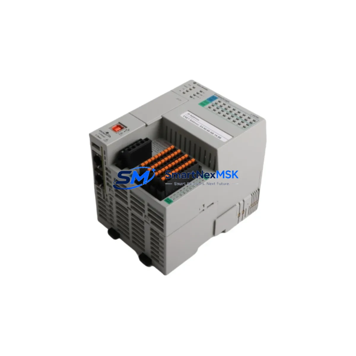
Allen-Bradley 1769-L18ERM-BB1B Retrofit-Ready EtherNet/IP Controller for CompactLogix 5370 Systems
The Allen-Bradley 1769-L18ERM-BB1B is a CompactLogix 5370 L1 series programmable logic controller designed for seamless integration into existing automation architectures. As legacy CompactLogix L32E, L35E, and MicroLogix 1500 platforms approach end-of-life, the 1769-L18ERM-BB1B has become the preferred retrofit-ready replacement for engineers managing aging control cabinets, distributed I/O panels, and multi-axis motion networks. With native EtherNet/IP support, 18 onboard I/O points, and full Studio 5000 Logix Designer compatibility, this controller delivers a smooth migration path without requiring a complete system redesign.
Before initiating a retrofit, engineers must verify several critical parameters. Power supply capacity is the first checkpoint: the 1769-L18ERM-BB1B draws from the CompactLogix 1769-PA2 or 1769-PB2 power supply, and any existing 24 VDC rail must be confirmed to support the combined load of the controller, expansion I/O, and field devices. Terminal wiring from the legacy system should be mapped against the new module’s I/O terminal block layout, as screw terminal pitch and signal groupings may differ from older 1769-L16ER-BB1B or 1769-L24ER-QB1B installations. Backplane interface compatibility with the 1769 compact I/O bus must also be confirmed, particularly when mixing older 1769-IQ16 digital input modules or 1769-OF4 analog output modules in the same rack.
Module addressing is another key consideration. When replacing a controller in an existing rack, the slot address assignments for all downstream 1769-IQ32 and 1769-OB32 I/O modules must be preserved in the new project file to avoid I/O tree mismatches. Program compatibility between the legacy RSLogix 5000 project and the Studio 5000 environment should be validated using Rockwell’s migration utility, with particular attention to any Add-On Instructions (AOIs) or Produced/Consumed tags that reference the old controller’s EtherNet/IP node address. HMI screens built on FactoryTalk View ME or PanelView Plus 7 terminals will require tag path updates if the controller IP address or slot configuration changes during the retrofit.
Communication link integrity is essential throughout the migration. The 1769-L18ERM-BB1B supports a single EtherNet/IP port operating at 10/100 Mbps, and any existing DeviceNet or ControlNet segments connected through a 1769-SDN scanner module or 1769-CNB bridge must be re-mapped to the new controller’s I/O tree. If the legacy system used a 1747-SN Remote I/O scanner for SLC 500 compatibility, a protocol migration to EtherNet/IP using a 1769-AENTR adapter is recommended to maintain field device connectivity without rewiring.
Upgrade Compatibility Table
| Parameter | Detail |
|---|---|
| Replaces / Compatible With | 1769-L16ER-BB1B, 1769-L24ER-QB1B, 1769-L27ERM-QBFC1B, MicroLogix 1500 (via protocol migration) |
| Communication Protocol | EtherNet/IP (10/100 Mbps), USB programming port |
| Onboard I/O | 18 points (10 DI / 8 DO, 24 VDC) |
| Expansion I/O Bus | 1769 Compact I/O (up to 8 modules) |
| Power Supply Compatibility | 1769-PA2 (120/240 VAC), 1769-PB2 (24 VDC) |
| Programming Software | Studio 5000 Logix Designer v21+, RSLogix 5000 (import) |
| Backplane Interface | 1769 Compact I/O bus, left-side expansion only |
| Installation Form Factor | DIN rail or panel mount, 1769 series footprint |
| HMI Compatibility | PanelView Plus 7, FactoryTalk View ME/SE |
| Commissioning Requirement | IP address assignment, I/O tree rebuild, tag path update |
| Warranty | 12 Months — covers hardware defects, DOA replacement, and functional verification |
Retrofit Planning for Existing Automation Systems
A successful retrofit begins with a full audit of the existing control cabinet. For systems built around the CompactLogix 5370 L1 platform, the 1769-L18ERM-BB1B slots directly into the existing 1769 compact I/O rack without mechanical modification. Engineers should document all existing 1769-IQ16 digital input modules, 1769-OB16 digital output modules, 1769-IF4 analog input modules, and 1769-OF4 analog output modules before beginning the swap. Each module’s slot position, I/O address, and wiring termination must be recorded to ensure the new controller’s I/O tree is rebuilt identically.
Power distribution within the cabinet requires careful review. The 1769-PA2 power supply must be confirmed to have sufficient headroom for the 1769-L18ERM-BB1B’s current draw plus all expansion modules. If the existing installation uses a 1769-PB2 DC power supply fed from a 24 VDC bus, verify that the bus voltage is stable under full load, particularly when 1769-IQ32 high-density input modules are present. For cabinets that also house a PowerFlex 525 or PowerFlex 755 drive on the same EtherNet/IP network, the network switch port configuration and IP addressing scheme must be updated to reflect the new controller node.
Communication module integration is a common retrofit challenge. If the legacy system used a 1769-L18ERM-BB1B predecessor with a 1769-SDN DeviceNet scanner, the DeviceNet node list must be exported and re-imported into the new controller project. For systems migrating from ControlNet to EtherNet/IP, a 1769-CNB ControlNet bridge module may need to remain in service temporarily during parallel operation. Programming cables such as the 1784-U2DHP USB-to-DH+ adapter or the standard USB-B programming cable should be prepared in advance for on-site commissioning. Spare 1769-ECR end caps and 1769-EXL left-end expansion cables should also be on hand to complete the mechanical assembly.
Downtime Control During System Migration
Minimizing production downtime during a controller swap requires a structured pre-migration checklist. Before powering down the existing system, the full RSLogix 5000 or Studio 5000 project file must be backed up, including all force tables, trend configurations, and alarm definitions. A complete I/O status snapshot should be captured to document the last known state of all field devices. If the system controls a continuous process, a safe-state procedure must be defined to bring the process to a hold condition without triggering safety interlocks or causing material loss.
During the physical swap, the 1769-L18ERM-BB1B can be installed in the existing rack while the power supply remains de-energized. All 1769 compact I/O modules remain in place, preserving field wiring. After power-up, the new controller will enter a faulted state until the correct project file is downloaded via the USB programming port or EtherNet/IP connection. Once the project is loaded and the I/O tree is verified, a controlled online edit session in Studio 5000 allows engineers to confirm tag values and force outputs before releasing the system to automatic mode. This approach typically reduces unplanned downtime to under two hours for a standard 8-module rack configuration.
For systems where continuous operation is critical, a parallel commissioning strategy is recommended. The new 1769-L18ERM-BB1B can be configured and tested offline using a bench rack with representative 1769-IQ16 and 1769-OB16 modules before the scheduled maintenance window. This allows full program verification, HMI tag path updates on the PanelView Plus 7 terminal, and EtherNet/IP network configuration to be completed without affecting the live system. The cutover then becomes a simple cable swap and project download, reducing the maintenance window to under 30 minutes in most cases.
Retrofit Support FAQ
Q: Is the 1769-L18ERM-BB1B a direct drop-in replacement for the 1769-L16ER-BB1B?
A: Yes, the 1769-L18ERM-BB1B is mechanically and electrically compatible with the 1769-L16ER-BB1B in the same 1769 compact I/O rack. The primary differences are increased onboard I/O count (18 vs. 16 points) and expanded EtherNet/IP motion axis support. The existing project file can be imported into Studio 5000 with minor tag path adjustments. No rewiring of the 1769 compact I/O expansion modules is required.
Q: What commissioning steps are required after installation?
A: After physical installation, assign a static IP address to the controller via the USB programming port using Studio 5000 Logix Designer. Rebuild the I/O tree to match the existing 1769 compact I/O module configuration, verify all EtherNet/IP device connections including any PowerFlex drives or PanelView terminals, and perform a controlled program download. Conduct a full I/O checkout by forcing each input and output point before releasing the system to automatic operation.
Q: Does the unit ship pre-tested and what does the 12-month warranty cover?
A: Yes. Each 1769-L18ERM-BB1B unit undergoes functional verification testing prior to shipment, including power-up, communication port check, and I/O point verification. The 12-month warranty covers hardware defects, dead-on-arrival (DOA) replacement, and any functional failures under normal operating conditions. Warranty claims are processed within 5 business days, with advance replacement available for critical production environments.
Q: Can this controller be used to replace a MicroLogix 1500 in an existing panel?
A: A direct drop-in replacement is not possible due to differences in I/O bus architecture and programming environment between the MicroLogix 1500 (1764 series) and the CompactLogix 1769 platform. However, a migration is fully achievable using a 1769-AENTR EtherNet/IP adapter to bridge existing 1769 expansion I/O, combined with a program conversion from RSLogix 500 to Studio 5000. This approach preserves field wiring while modernizing the control platform to support EtherNet/IP-based SCADA and HMI integration.
© 2026 SMARTNEXMSK. All rights reserved.
Original Source: https://smartnexmsk.com
Contact: [email protected] | +86 18259474341



