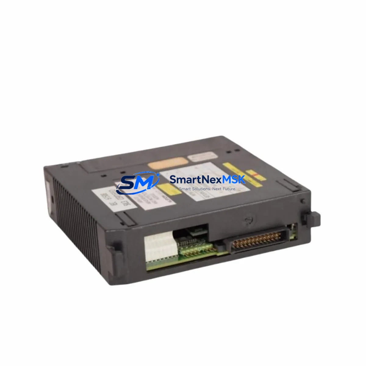
ALSTOM 8143-4002 Retrofit-Ready Digital Output Module for 8143 Series Control Systems
The ALSTOM 8143-4002 is a retrofit-ready digital output module engineered for seamless integration into ALSTOM 8143 Series Distributed Control Systems (DCS). As legacy power generation and industrial process control installations reach end-of-support milestones, the 8143-4002 provides a verified drop-in replacement path that preserves existing backplane wiring, rack architecture, and control logic — minimizing engineering rework and unplanned downtime during system modernization projects.
Whether you are replacing a failed unit on an operating plant, executing a planned control system upgrade, or building a critical spare inventory for a remote facility, the 8143-4002 is stocked, tested, and ready to ship with a 12-month warranty.
Upgrade Compatibility Table
| Parameter | Details |
|---|---|
| SKU / Part Number | 8143-4002 |
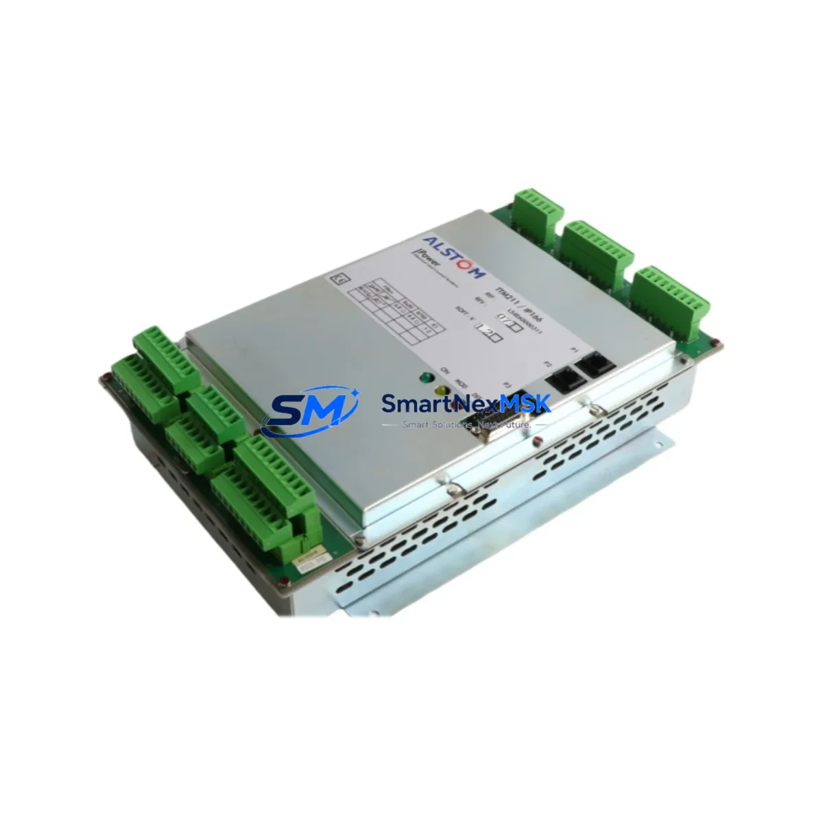
| Brand | ALSTOM |
| Compatible Series | ALSTOM 8143 Series DCS |
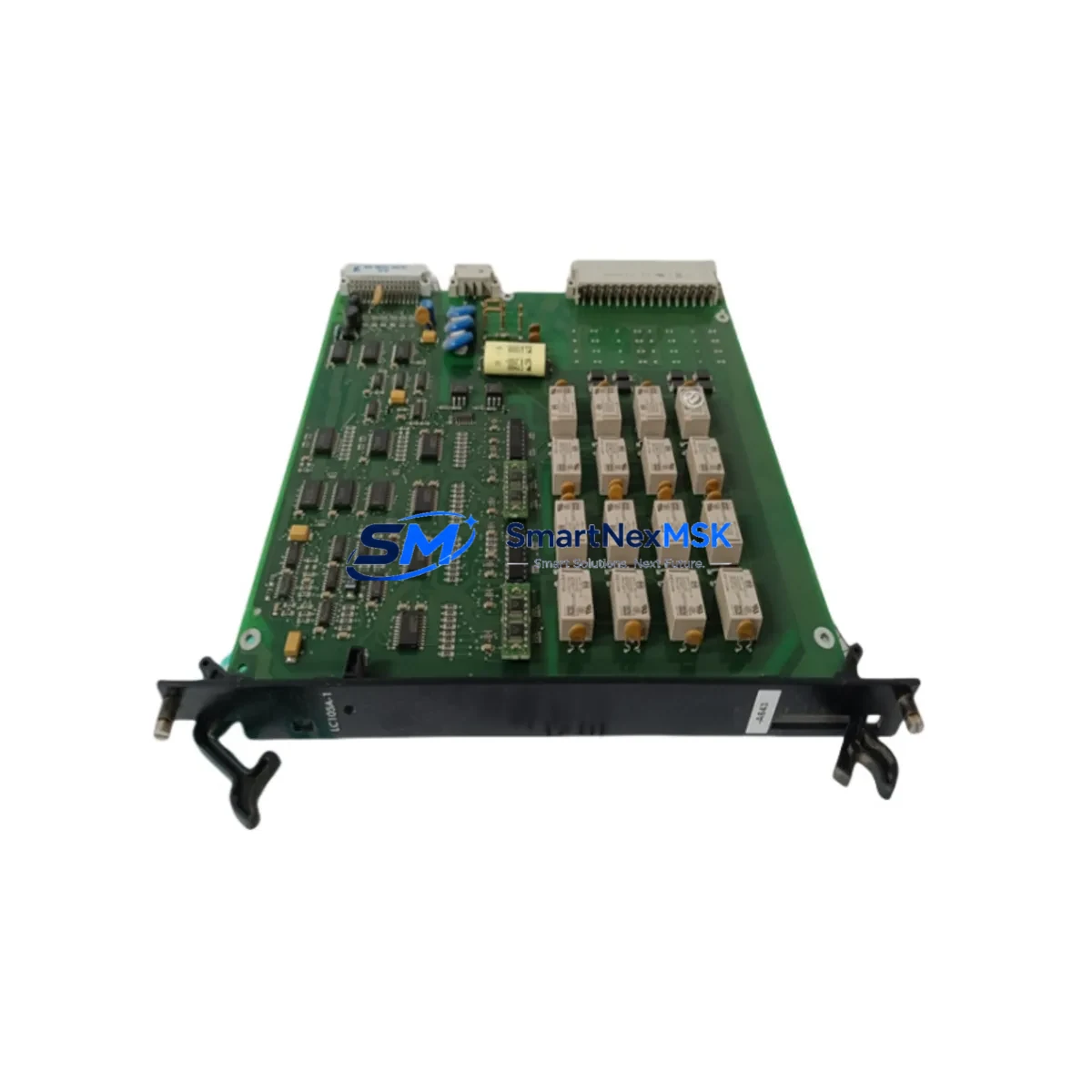
| Module Type | Digital Output Module |
| Backplane Interface | 8143 Series standard backplane connector; direct slot replacement |
| Installation Requirement | No hardware modification required; verify rack slot address before insertion |
| Communication Compatibility | Compatible with 8143 Series DCS communication bus; verify firmware revision with site engineer |
| Replacement Recommendation | Direct replacement for discontinued 8143-4002 units; confirm I/O channel mapping in controller configuration |
| Commissioning Notes | Perform loop check on all output channels; verify field terminal wiring continuity before energizing |
| Warranty | 12 Months — covers manufacturing defects and functional failure under normal operating conditions |
Retrofit Planning for Existing Automation Systems
Successful integration of the ALSTOM 8143-4002 into an existing control architecture requires a structured pre-installation review. Before removing the failed or obsolete module, site engineers should document the current rack configuration, including the slot position of the 8143-4002 relative to adjacent modules such as the ALSTOM 8143-4001 Digital Input Module and any installed 8143-4003 Analog Output Modules. Slot addressing in the 8143 Series DCS is position-dependent, and an incorrect slot assignment will prevent the controller from recognizing the replacement module.
Power supply capacity is a critical pre-check item. The 8143 Series rack is typically powered by a dedicated ALSTOM 8143-1001 Power Supply Module. Before adding or replacing output modules, verify that the available power budget on the backplane bus is sufficient to support the 8143-4002’s load, particularly in racks that have been expanded with additional 8143-4004 I/O Expansion Modules. Overloading the power rail is a common cause of intermittent module faults in aging DCS installations.
Terminal wiring on the 8143-4002 follows the standard 8143 Series field terminal block layout. If the original module’s terminal block is damaged or corroded, replacement with a compatible 8143 Series field termination assembly is recommended before reinstalling the new module. Label all field cables before disconnection and photograph the existing wiring arrangement to support accurate reconnection.
For sites migrating from older ALSTOM ALSPA or Contronic DCS platforms to the 8143 Series architecture, communication protocol mapping must be validated. The 8143 Series uses a proprietary DCS communication bus; integration with third-party SCADA systems or Modbus RTU / Profibus DP communication gateways requires configuration of the relevant communication module — typically an ALSTOM 8143-6001 Communication Interface Module — to ensure that digital output status data is correctly reflected in the supervisory layer.
HMI screen updates are frequently overlooked during module replacement projects. If the plant’s ALSTOM ALSPA P320 HMI or equivalent operator workstation references specific I/O tag names tied to the 8143-4002’s channel assignments, verify that tag bindings remain intact after the replacement. A mismatch between the HMI display and the physical output state can create operational confusion during post-commissioning handover.
For sites that require programming cable access during commissioning, ensure that the appropriate ALSTOM DCS programming interface cable and engineering workstation software are available on-site. Uploading the existing program from the controller before module replacement provides a verified backup and allows rapid restoration if configuration issues arise during the swap.
Downtime Control During System Migration
Minimizing production interruption during a digital output module replacement on an operating 8143 Series DCS requires careful sequencing. Where the process permits, place the affected output channels in manual mode at the DCS controller level before initiating the physical swap. This prevents spurious output signals from reaching field devices — such as solenoid valves, motor starters, or relay panels — during the module removal and reinsertion sequence.
If the 8143-4002 controls outputs that are part of a safety interlock or emergency shutdown (ESD) circuit, coordinate the replacement with the site safety officer and follow the applicable Management of Change (MOC) procedure. Bypassing safety outputs without authorization is a compliance risk and may void equipment warranties.
Once the replacement 8143-4002 is seated in the rack and the backplane connector is fully engaged, power up the rack and observe the module’s status indicators. A healthy module will complete its self-diagnostic cycle and report ready status to the DCS controller within the normal initialization window. If the controller does not recognize the module, verify the slot address configuration in the controller’s I/O assignment table and confirm that the module firmware version is compatible with the installed controller revision.
After successful initialization, perform a systematic channel-by-channel output test using the DCS engineering workstation’s force output function. Confirm field device response for each channel before returning the outputs to automatic control. Document the commissioning test results and retain them as part of the plant’s maintenance record. Total replacement time for a prepared team with the correct spare module and tools is typically under two hours, keeping planned maintenance windows well within acceptable limits.
Retrofit Support FAQ
Q1: Is the ALSTOM 8143-4002 a direct drop-in replacement for the original discontinued unit?
Yes. The 8143-4002 is designed as a form-fit-function replacement for the original ALSTOM 8143 Series digital output module. No hardware modification to the rack or backplane is required. Verify the slot address assignment in the DCS controller configuration before installation to ensure correct I/O mapping.
Q2: What pre-commissioning wiring checks are required before installing the replacement module?
Inspect all field terminal connections for corrosion, loose terminations, or damaged insulation. Verify that field cable labels match the I/O channel assignment documented in the plant’s loop drawings. Measure field device load impedance on each output channel to confirm it is within the module’s rated output capacity. Reconnect and torque all terminals to the manufacturer’s specification before energizing.
Q3: How is compatibility with the existing DCS controller and communication bus verified?
Compatibility is confirmed by matching the module’s hardware revision and firmware version against the controller’s supported module list, available in the ALSTOM 8143 Series system documentation. If the engineering workstation software version has been updated since the original installation, verify that the I/O driver for the 8143-4002 is included in the current software release. Contact our technical team with your controller firmware version for a pre-shipment compatibility check.
Q4: What does the 12-month warranty cover, and what is the return process?
The 12-month warranty covers manufacturing defects and functional failure under normal operating conditions from the date of shipment. It does not cover damage resulting from incorrect installation, overvoltage, or unauthorized modification. To initiate a warranty claim, contact our sales team with the order number, a description of the fault, and the module’s serial number. Replacement units are dispatched upon receipt and inspection of the returned module.
© 2026 SMARTNEXMSK. All rights reserved.
Original Source: https://smartnexmsk.com
Contact: sales@smartnexmsk.com | +86 18259474341