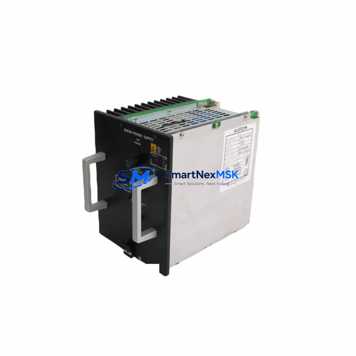
ALSTOM 8917-4003 Maintenance-Ready Spare for 8917 Series Automation
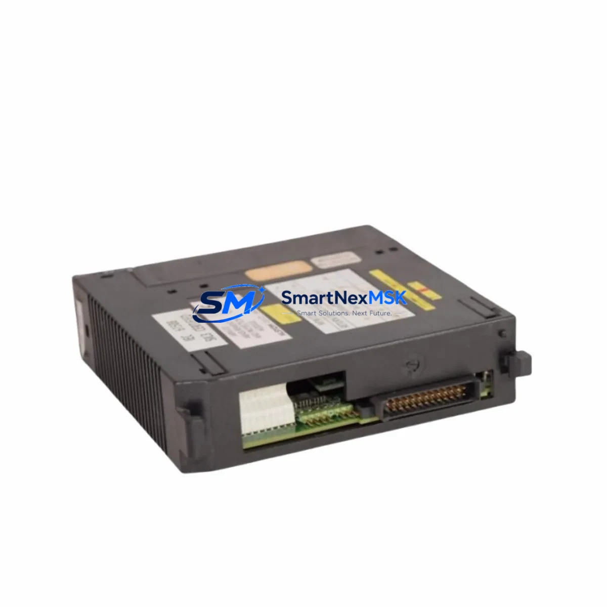
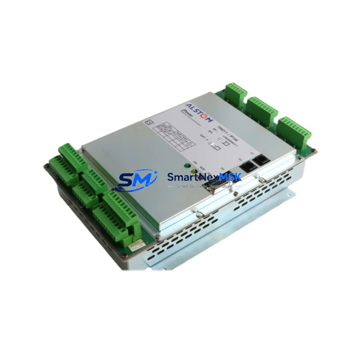
The ALSTOM 8917-4003 is an original DCS power supply module engineered for the ALSTOM 8917 Series distributed control system platform. Designed to deliver stable, regulated DC power to field I/O racks, controller backplanes, and communication buses, this module is a critical component in continuous-process industries including power generation, petrochemical refining, pulp and paper, and water treatment. When this module fails or degrades, the downstream impact is immediate: loss of I/O scan, controller fault, and potential unplanned shutdown. Maintaining a verified spare on the shelf is the single most effective strategy for minimizing mean time to repair (MTTR).
Every 8917-4003 unit supplied by SMARTNEXMSK is sourced from original ALSTOM manufacturing channels, individually bench-tested under load prior to shipment, and backed by a 12-month warranty. We support maintenance engineers and procurement teams who need a reliable, fast-delivery replacement without the lead times associated with OEM new-buy orders.
Spare Maintenance Table
| Parameter | Specification / Detail |
|---|---|
| Part Number | 8917-4003 |
| Brand | ALSTOM |
| Series | 8917 Series DCS |
| Module Type | DCS Power Supply Module |
| Application | Distributed Control System (DCS) rack power distribution |
| Compatibility | ALSTOM 8917 Series controller racks and I/O backplanes |
| Origin | Original ALSTOM manufacture |
| Installation | Rack-mount, hot-swap capable (verify with site SOP) |
| Operating Environment | Industrial control cabinet; standard IEC 61131-2 conditions |
| Maintenance Interval | Inspect annually; replace on fault indication or output deviation |
| Warranty | 12 months from date of shipment |
| Pre-shipment Test | Full load bench test; functional verification |
| Lead Time | In stock — same or next business day dispatch |
Maintenance Planning for Continuous Operation
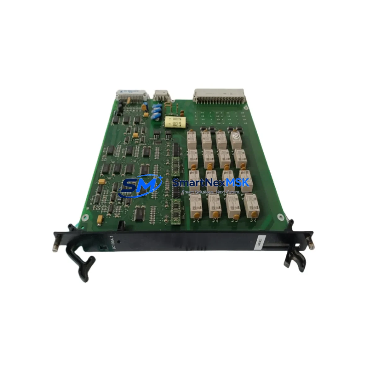
A power supply module failure in a DCS rack rarely occurs in isolation. When the ALSTOM 8917-4003 is flagged for replacement during a planned outage or emergency callout, a disciplined maintenance engineer will use the opportunity to inspect the entire power distribution chain within the control cabinet. Begin with the 8917 Series controller module itself — verify firmware integrity and check for any latent fault codes that may have been masked by the power anomaly. Inspect the 8917 Series I/O modules seated in the same rack; a power transient can stress analog input cards and digital output modules, causing intermittent signal errors that only surface under load.
Check the 24 VDC field power distribution terminals and associated terminal blocks for signs of overheating, loose connections, or insulation degradation. Examine the DIN-rail mounted circuit breakers and fuse holders upstream of the power supply — a nuisance trip or a slow-blow fuse that has partially degraded will cause the replacement module to fail prematurely. If the cabinet includes a redundant power supply module (a second 8917-series PSU in parallel), test its output voltage and current-sharing behavior before returning the system to service.
For cabinets that also house ALSTOM 8917 Series communication modules — such as Modbus RTU, PROFIBUS DP, or Ethernet gateway cards — verify that the communication bus recovers cleanly after power restoration. A corrupted node address table or a stuck communication watchdog can prevent the DCS from re-establishing full I/O scan even after the power supply is replaced. Similarly, inspect any signal isolators or loop-powered transmitter barriers in the same cabinet; these devices are sensitive to supply voltage ripple and may require recalibration after a power event.
If the site operates an operator HMI or engineering workstation connected to the 8917 Series DCS, confirm that the historian and alarm server have correctly logged the fault event and that no spurious process alarms remain active. Finally, review the UPS or battery backup system feeding the control cabinet — a degraded UPS battery is frequently the root cause of power supply module stress in aging DCS installations.
Site Replacement Workflow
Step 1 — Isolation and permit: Obtain a valid permit to work. Isolate the affected rack from field wiring per site LOTO procedure. Do not assume the rack is de-energized based on the PSU fault indicator alone.
Step 2 — Document current state: Record all active alarms, I/O states, and controller status before removal. Photograph wiring and module positions.
Step 3 — Module extraction: Release the module locking lever and slide the 8917-4003 out of the rack slot. Inspect the backplane connector for bent pins or carbon tracking.
Step 4 — Spare installation: Insert the replacement ALSTOM 8917-4003 and seat firmly. Verify the module status LED sequence matches the expected power-on behavior described in the ALSTOM 8917 Series hardware manual.
Step 5 — System restoration: Re-enable field wiring, restore controller scan, and confirm all I/O channels return to healthy status. Clear latched alarms only after process values are verified stable.
Step 6 — Documentation: Update the site maintenance log, record the replaced module serial number, and flag the faulty unit for return or failure analysis. Replenish the spare parts inventory immediately to maintain site readiness.
This workflow is designed to minimize downtime and ensure system compatibility is maintained throughout the replacement process. The ALSTOM 8917-4003 is a direct form-fit-function replacement for the original module — no firmware reconfiguration or rack address reassignment is required in standard installations.
Spare Parts Support FAQ
Q1: Is the 8917-4003 supplied by SMARTNEXMSK an original ALSTOM module?
Yes. All units are sourced from original ALSTOM manufacturing channels. Each module undergoes individual functional testing under load before shipment. A test report is available on request.
Q2: What is the recommended spare parts inventory strategy for the 8917 Series DCS?
For critical continuous-process sites, we recommend holding a minimum of one 8917-4003 power supply module per installed rack, plus one spare for every four I/O modules in service. Review your spare parts list annually against the installed base and replace any module that has exceeded 10 years of service life or shows output voltage drift beyond ±2%.
Q3: Can the 8917-4003 replace older ALSTOM 8917 Series power supply variants?
In most cases, yes — the 8917-4003 is designed as a compatible replacement within the 8917 Series rack architecture. However, always verify the rack slot designation and backplane connector type against your site’s as-built drawings before installation. Contact our technical team with your existing module label information if you require compatibility confirmation.
Q4: What does the 12-month warranty cover?
The warranty covers manufacturing defects and functional failure under normal operating conditions for 12 months from the date of shipment. It does not cover damage resulting from incorrect installation, overvoltage events, or physical mishandling. SMARTNEXMSK provides advance replacement support for warranty claims to minimize site downtime.
© 2026 SMARTNEXMSK. All rights reserved.
Original Source: https://smartnexmsk.com
Contact: sales@smartnexmsk.com | +86 18259474341