ASML 4022.436.7817 Maintenance-Ready Spare for TAB113 TAB217 Automation
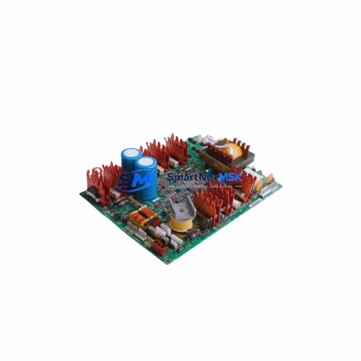
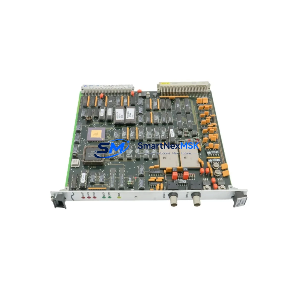
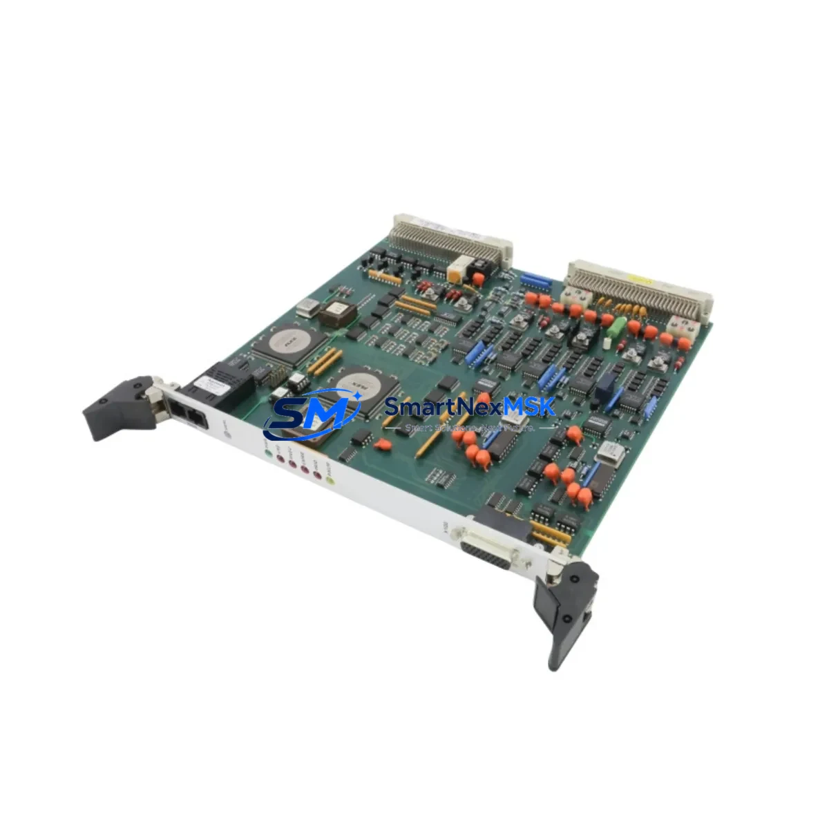
The ASML 4022.436.7817 PCB Assembly (2L81-050043-83, TAB113-1/I01-LF, TAB217-8/PC2-LF, 300V) is a critical original spare component for ASML lithography and semiconductor automation systems. For maintenance engineers managing high-availability fab environments, unplanned downtime caused by PCB-level failures in the TAB113 or TAB217 control subsystems can result in significant production loss. Sourcing a verified, tested replacement unit — rather than waiting on OEM lead times — is the most effective strategy for rapid downtime recovery and sustained system uptime.
This unit is supplied as an original spare, fully tested prior to shipment, and backed by a 12-month warranty. It is suitable for direct replacement in ASML TAB113-1/I01-LF and TAB217-8/PC2-LF board positions, operating at 300V nominal. Each unit undergoes functional verification before dispatch to ensure compatibility and reliability in live production environments.
Spare Maintenance Table
| Parameter | Specification |
|---|---|
| Part Number | 4022.436.7817 |
| Internal Reference | 2L81-050043-83 |
| Compatible Boards | TAB113-1/I01-LF, TAB217-8/PC2-LF |
| Rated Voltage | 300V |
| Product Type | PCB Assembly |
| Brand / OEM | ASML |
| Origin | Netherlands |
| Weight | 2,600 g |
| Condition | Original Spare, Tested Before Shipment |
| Application | ASML Lithography Systems, Semiconductor Fab Automation |
| Installation Environment | Cleanroom-compatible, controlled ESD environment required |
| Maintenance Recommendation | Inspect board connectors, verify bus voltage, check for thermal stress marks before installation |
| Warranty | 12 Months from date of shipment |
Maintenance Planning for Continuous Operation
When replacing the ASML 4022.436.7817 PCB Assembly in a TAB113 or TAB217 subsystem, a thorough site inspection of the surrounding electrical environment is essential to prevent repeat failures and ensure stable recommissioning. Maintenance engineers should begin by verifying the integrity of the 300V DC bus supply feeding the board slot — any voltage ripple or transient overvoltage condition may have contributed to the original failure and must be resolved before installing the replacement unit.
The backplane connector and board-edge interface should be inspected for oxidation, bent pins, or contamination. In ASML control cabinets, the TAB113 and TAB217 boards typically share a common backplane with adjacent I/O interface boards, power distribution modules, and communication interface cards. These components — including the local 24VDC auxiliary power supply module, the I/O expansion board, and the inter-board ribbon cable assemblies — should all be checked for continuity and correct seating.
Signal isolation between the PCB assembly and downstream sensor or actuator circuits is another critical checkpoint. If the system uses signal isolators or optocoupler-based interface modules between the TAB217 output stage and field devices, these should be tested for correct isolation resistance before the new board is powered up. Fuse holders and protection fuses on the 300V supply rail should be inspected and replaced if any signs of thermal stress are present.
For systems with integrated HMI panels or operator terminals connected to the TAB113 control loop, verify that the HMI communication link — typically RS-232 or proprietary ASML serial protocol — is intact and that the terminal is not reporting any persistent fault codes that could indicate a deeper system issue beyond the PCB assembly itself. Communication modules and protocol converters in the same control cabinet should be logged and their firmware versions confirmed as compatible with the replacement board revision.
Procurement engineers building a spare parts inventory for ASML lithography lines should consider stocking the 4022.436.7817 alongside related consumables and wear items: terminal block assemblies, DIN rail-mounted relay modules, 300V-rated fuse cartridges, and ESD-safe board extraction tools. A well-structured spare parts kit reduces mean time to repair (MTTR) and supports planned preventive maintenance schedules without emergency procurement delays.
Site Replacement Workflow
Before beginning the replacement procedure, ensure the ASML system is in a safe, de-energized state with all 300V supply rails confirmed off using a calibrated multimeter. Follow ASML’s lockout/tagout procedure for the relevant control cabinet. Remove the faulty 4022.436.7817 board by releasing the board ejector levers and sliding the assembly clear of the backplane — avoid flexing the board or applying lateral force to the connector edge.
Inspect the replacement unit’s board revision marking and confirm it matches the required TAB113-1/I01-LF or TAB217-8/PC2-LF designation. Insert the new board firmly and evenly into the backplane slot, ensuring full connector engagement. Re-energize the 300V supply rail and monitor the system status indicators for the expected initialization sequence. If the ASML system controller reports a board recognition fault, verify the board address jumper or DIP switch settings match the original configuration.
For legacy ASML systems where the original TAB113 or TAB217 board revision has been superseded, the 4022.436.7817 assembly provides a compatible replacement path that avoids the need for full subsystem upgrades. This extends the operational life of existing lithography equipment and defers capital expenditure on system modernization — a key consideration for fabs managing aging installed bases with limited upgrade budgets.
After successful installation, document the replacement in the site maintenance log, record the new board serial number, and update the spare parts inventory accordingly. Schedule a follow-up inspection at the next planned maintenance window to verify sustained performance under normal operating load.
Spare Parts Support FAQ
Q: Is the ASML 4022.436.7817 compatible with both TAB113-1/I01-LF and TAB217-8/PC2-LF board positions?
A: Yes. The 4022.436.7817 PCB Assembly is designed for use in both TAB113-1/I01-LF and TAB217-8/PC2-LF slots within ASML control systems. Always confirm the board revision marking and backplane address configuration before installation.
Q: What testing is performed before shipment?
A: Each unit undergoes functional verification prior to dispatch, including power-on testing and connector integrity checks. A test report is available upon request. All units are shipped with ESD-protective packaging.
Q: What does the 12-month warranty cover?
A: The 12-month warranty covers manufacturing defects and functional failures under normal operating conditions. It does not cover damage resulting from incorrect installation, overvoltage events, or physical mishandling. Warranty claims are processed via our technical support team.
Q: How quickly can this spare part be shipped, and do you support long-term supply agreements?
A: In-stock units are typically dispatched within 1–3 business days. For customers requiring ongoing supply continuity for ASML maintenance programs, we support long-term supply agreements and can reserve inventory against forecasted demand. Contact our team to discuss your requirements.
© 2026 SMARTNEXMSK. All rights reserved.
Original Source: https://smartnexmsk.com
Contact: [email protected] | +86 18259474341