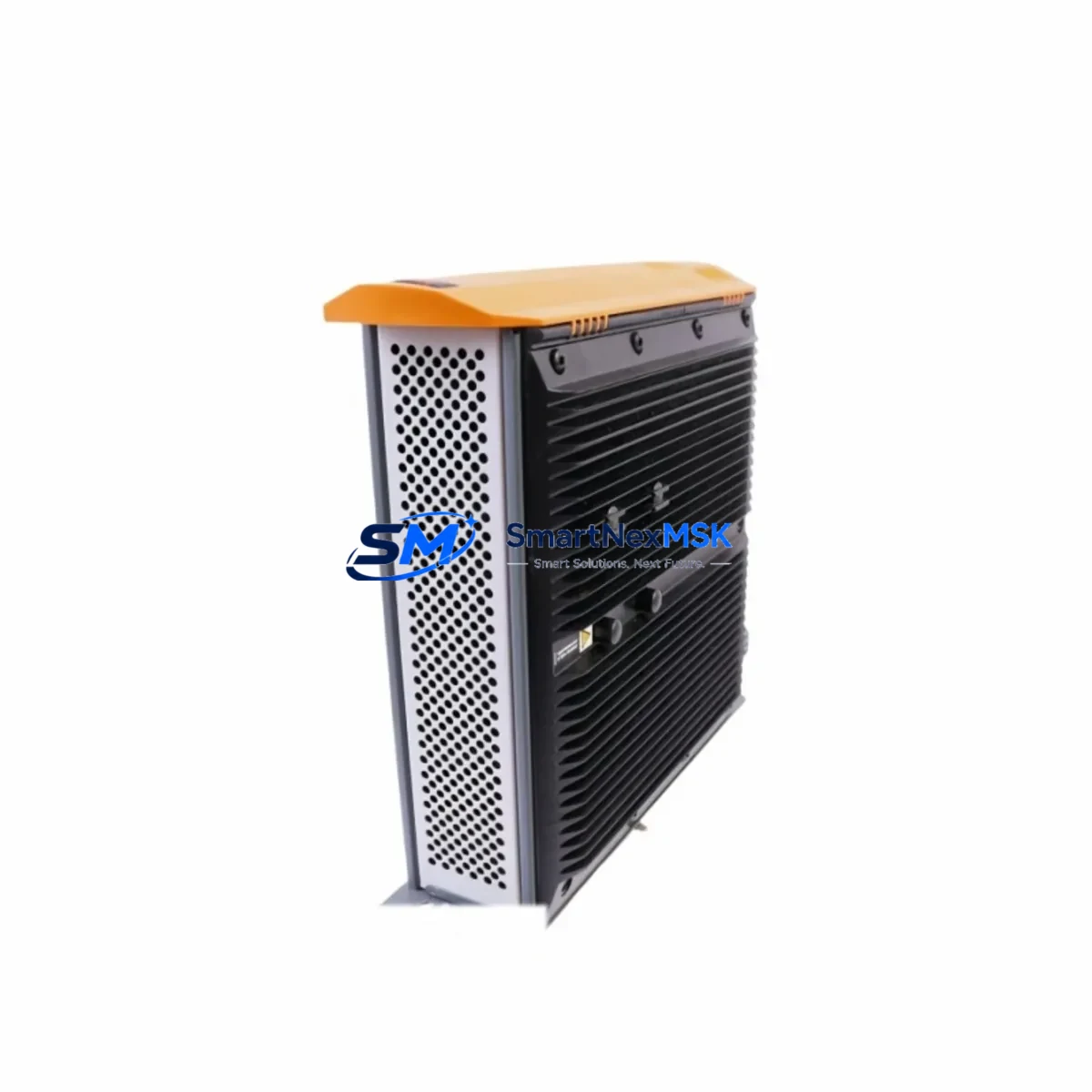
B&R 5PC810.5X01-00 Retrofit-Ready HMI for Power Panel 800: Seamless Compatibility and Legacy System Upgrade
The B&R 5PC810.5X01-00 is a high-performance industrial Panel PC designed for the Power Panel 800 series, offering a proven retrofit path for aging automation systems across manufacturing, energy, and process control industries. As original B&R Power Panel 800 units approach end-of-life or become increasingly difficult to source, the 5PC810.5X01-00 provides a direct-fit replacement that preserves existing backplane connections, terminal wiring layouts, and POWERLINK communication infrastructure — minimizing re-engineering effort and protecting your capital investment in legacy control architecture.
Whether you are replacing a failed unit on an active production line, upgrading a control cabinet as part of a planned modernization project, or sourcing a verified spare to reduce unplanned downtime risk, the 5PC810.5X01-00 delivers the hardware reliability and software compatibility that industrial engineers demand. Each unit is pre-tested before shipment and backed by a 12-month warranty covering hardware defects under normal operating conditions.
Upgrade Compatibility Table
| Parameter | Details |
|---|---|
| SKU / Part Number | 5PC810.5X01-00 |
| Series | B&R Power Panel 800 |
| Form Factor | Panel-mount Industrial PC (front-panel installation) |
| Display Interface | Integrated TFT touchscreen, compatible with existing HMI frame cutout |
| Communication Protocol | POWERLINK (Ethernet POWERLINK V2), Ethernet TCP/IP |
| Backplane / Rack Interface | Compatible with standard Power Panel 800 backplane connectors |
| I/O Expansion | Supports X20 and X67 I/O modules via POWERLINK bus |
| Programming Environment | B&R Automation Studio (AS 4.x compatible) |
| Replacement Compatibility | Direct replacement for Power Panel 800 series; verify firmware version before swap |
| Installation Requirement | Panel cutout dimensions must match; DIN rail or panel-mount bracket required |
| Commissioning Note | Re-upload Automation Studio project; verify POWERLINK node address and I/O mapping |
| Warranty | 12 months from date of shipment, hardware defects under normal use |
Retrofit Planning for Existing Automation Systems
A successful retrofit of the B&R 5PC810.5X01-00 into an existing Power Panel 800 installation requires careful pre-migration planning across several system layers. Before removing the legacy unit, engineers should document the existing POWERLINK network topology, including node addresses assigned to all connected X20 I/O modules, X20 digital input/output stations, and any X20 communication modules handling serial or fieldbus bridging. Photographs of terminal wiring on the existing backplane and any X20 terminal blocks should be taken as reference during reinstallation.
Power supply verification is a critical first step. Confirm that the 24 VDC supply feeding the Power Panel 800 backplane meets the current draw requirements of the 5PC810.5X01-00 under full I/O load. If the existing X20 power supply module (such as an X20PS9400 or equivalent) is aging, this is an ideal time to replace it alongside the Panel PC to avoid a secondary failure shortly after commissioning. Similarly, inspect the backplane itself for corrosion or damaged connector pins before installing the replacement unit.
For systems using POWERLINK as the primary motion and I/O bus, the 5PC810.5X01-00 acts as the POWERLINK Managing Node (MN). After installation, the Automation Studio project must be re-transferred to the new hardware. Engineers should verify that the CPU module configuration within Automation Studio matches the hardware revision of the replacement unit. If the legacy system used an older Automation Runtime version, a controlled runtime upgrade may be required — this should be tested in a staging environment before live deployment.
HMI screen migration is another key consideration. If the existing Power Panel 800 ran Visual Components or mapp View HMI applications, these projects should be backed up from the original unit (if still accessible) or reconstructed from the Automation Studio project archive. Verify that all HMI tag bindings, alarm configurations, and trend data connections remain intact after the hardware swap. For systems with third-party SCADA connectivity via OPC UA or Modbus TCP, re-validate the communication link after the new unit is online.
In control cabinets where the Power Panel 800 is integrated alongside X20 analog input modules, X20 counter modules, or X20 safety modules (X20SL8100 series), ensure that the safety program and safety parameter sets are re-validated according to the machine’s functional safety documentation. Safety-rated I/O requires re-commissioning after any controller hardware change.
Downtime Control During System Migration
Minimizing production downtime during a Power Panel 800 retrofit is achievable with disciplined pre-staging and a structured cutover plan. The recommended approach is to pre-configure the replacement 5PC810.5X01-00 offline using Automation Studio before the maintenance window begins. Load the full Automation Studio project — including the PLC program, HMI application, motion configuration, and I/O mapping — onto the new unit in a bench environment. Verify that the unit boots correctly, the POWERLINK network initializes, and all configured I/O modules are recognized before bringing the unit to the production floor.
During the cutover window, follow a structured sequence: isolate the machine from the production line, de-energize the control cabinet, document and photograph all wiring, remove the legacy Power Panel 800, install the 5PC810.5X01-00 into the same panel cutout, reconnect all terminal wiring and POWERLINK cables, restore power, and verify system startup. The entire physical swap typically takes 30–90 minutes for a prepared technician. Post-swap commissioning — including I/O verification, HMI screen validation, motion axis homing, and a supervised production trial run — should be allocated an additional 1–3 hours depending on system complexity.
To protect the original program logic, always maintain a version-controlled backup of the Automation Studio project in a secure location before beginning any hardware replacement. If the legacy unit is still partially functional, use Automation Studio’s online transfer function to extract the current runtime project as a final backup immediately before the cutover. This ensures that even if undocumented field modifications were made to the running program, they are captured before the old hardware is removed.
Retrofit Support FAQ
Q1: Is the 5PC810.5X01-00 a direct drop-in replacement for all Power Panel 800 variants?
The 5PC810.5X01-00 is compatible with the Power Panel 800 series backplane and panel cutout dimensions. However, engineers should verify the specific hardware revision and firmware version of the legacy unit against the replacement before installation. Minor differences in display resolution or CPU performance between sub-variants may require HMI layout adjustments in Automation Studio.
Q2: What wiring changes are required during the retrofit?
In most cases, no wiring changes are required if the replacement unit is installed into the same backplane position. Terminal block wiring connected to X20 I/O modules remains unchanged. If the legacy unit used custom cable harnesses for serial communication (RS232/RS485) or USB peripherals, verify connector compatibility with the 5PC810.5X01-00’s port layout before finalizing the installation plan.
Q3: How is the unit tested before shipment?
Each 5PC810.5X01-00 unit undergoes a pre-shipment functional test covering power-on self-test, display initialization, POWERLINK interface verification, and storage media integrity check. Units are shipped with original or equivalent packaging to prevent transit damage. A test report is available upon request for quality-critical applications.
Q4: What does the 12-month warranty cover?
The 12-month warranty covers hardware defects arising under normal operating conditions from the date of shipment. It does not cover damage resulting from incorrect installation, overvoltage events, environmental contamination, or unauthorized modification. Warranty claims are processed with a replacement-first policy to minimize customer downtime. Contact [email protected] to initiate a warranty claim.
© 2026 SMARTNEXMSK. All rights reserved.
Original Source: https://smartnexmsk.com
Contact: [email protected] | +86 18259474341