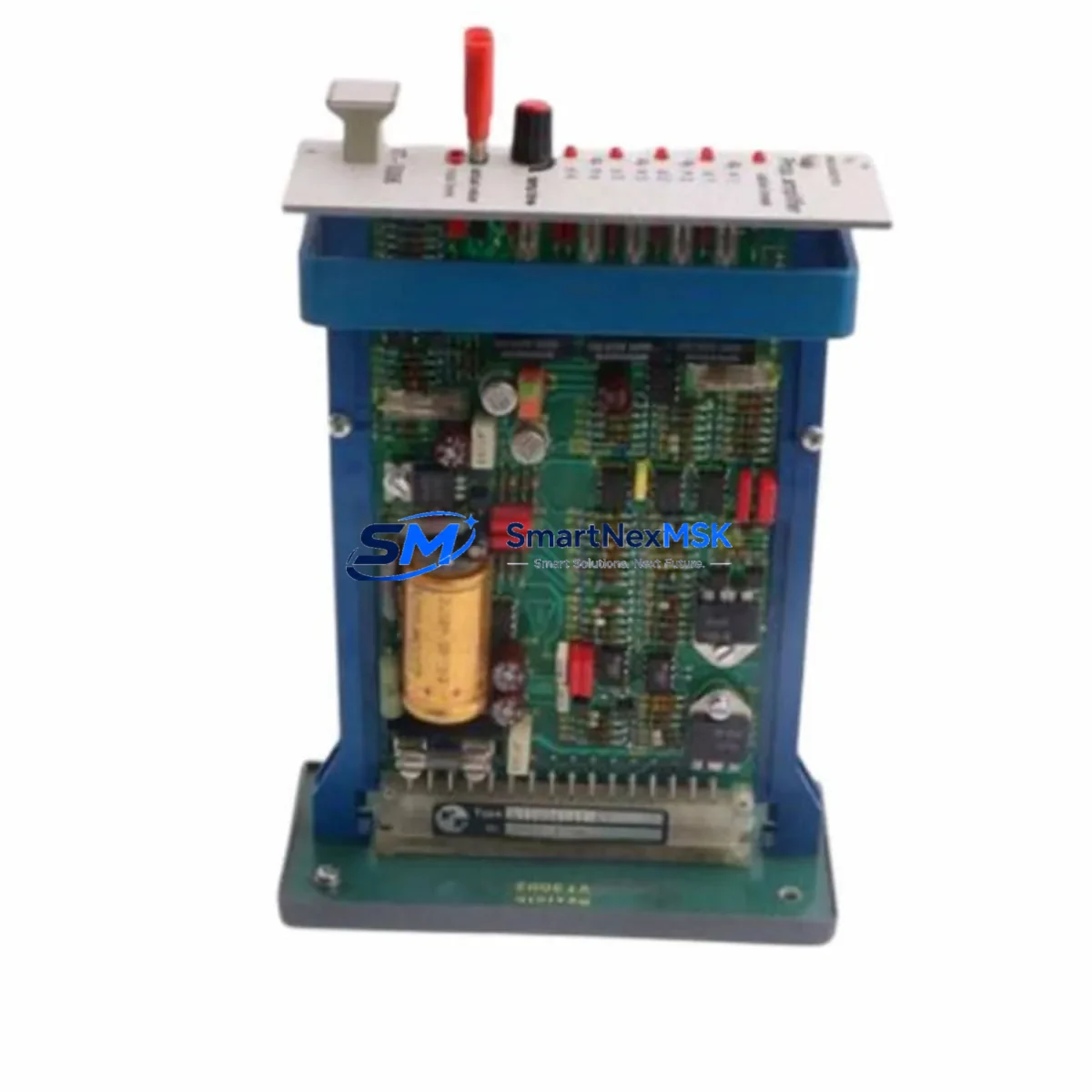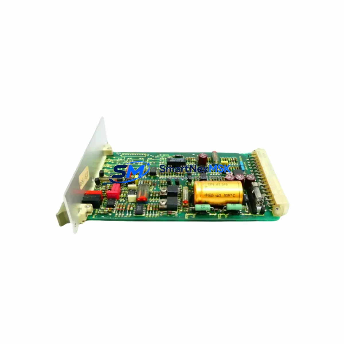
Bosch Rexroth VT-3014-S35-R5 Spare for VT-3014 Automation: Spare Parts Replacement & Industrial Downtime Risk Control
The Bosch Rexroth VT-3014-S35-R5 is a dual-channel proportional amplifier card engineered for precise electrohydraulic control within the VT-3014 series platform. In industrial maintenance environments — from press lines and injection molding machines to steel mill hydraulic systems — this amplifier card serves as the critical interface between the PLC command signal and the proportional directional control valve. When this card fails or degrades, the entire hydraulic axis loses closed-loop authority, resulting in uncontrolled actuator drift, positioning errors, and unplanned production downtime. Stocking a verified replacement unit of the VT-3014-S35-R5 is therefore a fundamental element of any serious spare parts management strategy for Rexroth-based hydraulic control systems.
Spare Maintenance Table
| Parameter | Specification |
|---|---|
| SKU / Part Number | VT-3014-S35-R5 |
| Brand | Bosch Rexroth |
| Series | VT-3014 |
| Product Type | Proportional Amplifier Card |
| Channels | Dual-channel (2-axis) |
| Supply Voltage | 24 VDC (±15% tolerance) |
| Output Current | Up to 2.5 A per channel (solenoid drive) |
| Enable Input | Digital enable signal, PLC-compatible |
| Command Signal Input | ±10 V differential analog or PWM |
| Ramp Function | Adjustable ramp-up / ramp-down via onboard potentiometer |
| Compatibility | Bosch Rexroth VT-3014 series proportional valves; replaces earlier VT-3014-S3x revisions |
| Mounting | DIN rail or panel-mount sub-rack (VT-3000 series rack compatible) |
| Operating Temperature | 0°C to +55°C |
| Protection Class | IP20 (card-level); install in sealed control cabinet |
| Origin | Germany |
| Warranty | 12 Months — tested and verified before shipment |
Maintenance Planning for Continuous Operation
When a maintenance or procurement engineer schedules replacement of the VT-3014-S35-R5, the scope of inspection should extend well beyond the amplifier card itself. The card operates within a tightly coupled electrical and hydraulic control loop, and adjacent components are subject to the same aging, vibration, and thermal stress cycles.
Begin with the 24 VDC power supply module feeding the amplifier rack — a sagging or noisy supply rail is a leading cause of premature amplifier card failure and erratic valve response. Verify output voltage under load and check ripple with an oscilloscope. If the rack uses a Rexroth VT-NE30 or equivalent regulated power supply, inspect its capacitors and output terminals at the same interval as the amplifier card replacement.
Next, inspect the analog command signal wiring from the PLC analog output module. Shielded cable integrity, terminal block torque, and ground loop isolation all affect the ±10 V command signal quality. A degraded signal will cause the VT-3014-S35-R5 to output unstable solenoid current even when the card itself is healthy. Check the PLC analog output card (such as a Siemens SM 332 or equivalent) for drift or channel offset errors at this time.
The proportional solenoid coils on the associated directional control valve should be resistance-tested and inspected for insulation breakdown. Coil resistance out of specification will cause the VT-3014-S35-R5 to operate in current-limiting mode continuously, accelerating thermal wear on the output stage. If the valve body has been in service for more than five years, consider scheduling a valve spool inspection and seal kit replacement concurrently.
Within the control cabinet, inspect the terminal blocks and DIN rail connectors for oxidation and loose crimps — particularly on the enable signal circuit and the feedback potentiometer wiring if a position transducer (LVDT or draw-wire encoder) is part of the closed-loop configuration. A faulty signal isolator or signal conditioner between the transducer and the amplifier card feedback input is a common source of oscillation and hunting that is frequently misdiagnosed as amplifier card failure.
For systems using Profibus DP or CANopen fieldbus communication to the hydraulic axis controller, verify the fieldbus termination resistors and cable continuity. A degraded fieldbus segment can cause intermittent enable signal dropouts that appear as amplifier card faults in the PLC diagnostic buffer. Check the fieldbus communication module and its connector seating in the rack backplane.
Finally, review the circuit breaker and fuse protection on the amplifier rack supply circuit. A slow-blow fuse rated for the correct current (typically 4–6 A for a dual-channel rack) protects the card from upstream fault propagation. Replace fuses at the same time as the amplifier card to eliminate latent protection failures. If the cabinet includes a 24 VDC relay output module for enable signal switching, test relay contact resistance and replace any relay showing contact bounce or elevated resistance above 0.5 Ω.
Site Replacement Workflow
Replacing the VT-3014-S35-R5 on-site is a structured process that, when executed correctly, restores hydraulic axis control within a single maintenance window — typically 30 to 90 minutes for a prepared technician with a verified spare unit in hand.
Step 1 — Preparation: Before powering down, record all onboard potentiometer settings (ramp-up, ramp-down, dither frequency, and gain) using a calibration sheet or photograph. These settings are machine-specific and must be replicated on the replacement card. If the machine uses a Rexroth parameterization tool or a stored parameter set in the PLC, retrieve the last saved configuration.
Step 2 — Safe Isolation: De-energize the amplifier rack supply circuit at the circuit breaker. Verify zero voltage at the rack power terminals with a calibrated multimeter. Lock out / tag out per site safety procedure. Depressurize the hydraulic circuit if the valve controls a load-holding function.
Step 3 — Card Removal and Inspection: Extract the VT-3014-S35-R5 from the sub-rack using the card ejector levers. Inspect the card edge connector and backplane connector for corrosion, bent pins, or carbon tracking. Clean the backplane connector with contact cleaner if contamination is present.
Step 4 — Replacement Card Installation: Insert the verified replacement VT-3014-S35-R5 into the same slot. Confirm the card is fully seated and the ejector levers are locked. Reconnect any external wiring harnesses if the card uses front-panel connectors.
Step 5 — Parameter Restoration and Commissioning: Restore potentiometer settings from the recorded values. Re-energize the rack supply. Apply the PLC enable signal and command a slow ramp to verify solenoid current output and valve response. Confirm axis positioning accuracy against the machine’s acceptance criteria before returning to production.
This workflow is compatible with replacing earlier VT-3014-S3x revision cards, as the R5 revision maintains backward electrical and mechanical compatibility within the VT-3014 series sub-rack platform.
Spare Parts Support FAQ
Q1: What is the recommended spare parts lifecycle strategy for the VT-3014-S35-R5?
For machines with continuous production schedules, maintain at least one verified replacement VT-3014-S35-R5 on-site at all times. The amplifier card’s MTBF under normal operating conditions exceeds 50,000 hours, but thermal cycling, power quality events, and vibration can accelerate failure. A proactive replacement at 8–10 years of service life, combined with a functional test of the outgoing card, is recommended practice.
Q2: How is compatibility with my existing VT-3014 series valve confirmed before shipment?
Each VT-3014-S35-R5 unit we supply is tested against standard VT-3014 series electrical parameters — supply voltage response, output current linearity, enable signal threshold, and ramp function — prior to shipment. We verify the revision level and confirm compatibility with your valve model and rack configuration based on the information you provide at the time of order.
Q3: Can the VT-3014-S35-R5 replace older VT-3014-S30 or VT-3014-S32 revision cards?
Yes. The R5 revision is a direct functional replacement for earlier S30, S32, and S34 revision cards within the VT-3014 series. The card maintains the same connector pinout, supply voltage requirements, and command signal interface. Potentiometer positions may require adjustment to match the original machine calibration after installation.
Q4: What does the 12-month warranty cover, and what is the support process?
The 12-month warranty covers manufacturing defects and functional failure under normal operating conditions. Each unit is tested and documented before shipment. In the event of a warranty claim, contact our technical support team with the order reference and a description of the fault symptom. We will arrange priority replacement shipment to minimize your production downtime.
© 2026 SMARTNEXMSK. All rights reserved.
Original Source: https://smartnexmsk.com
Contact: [email protected] | +86 18259474341