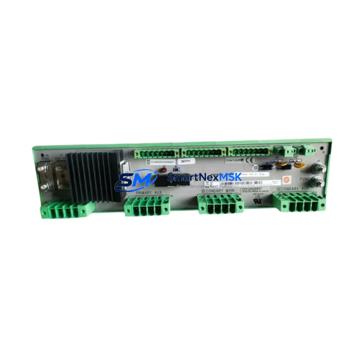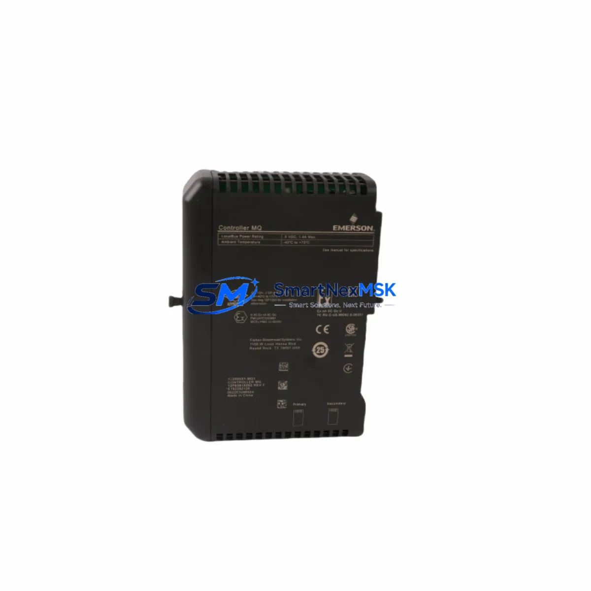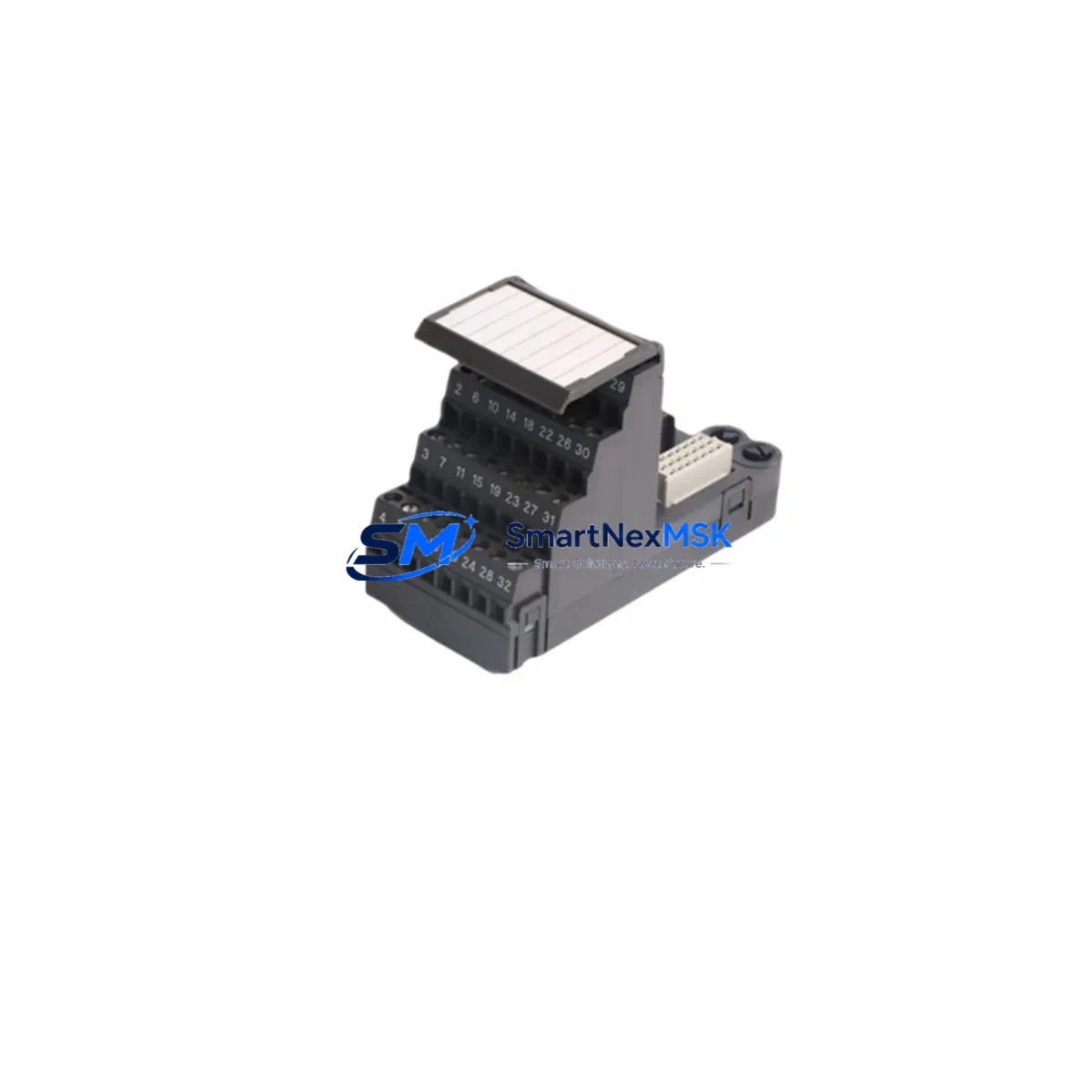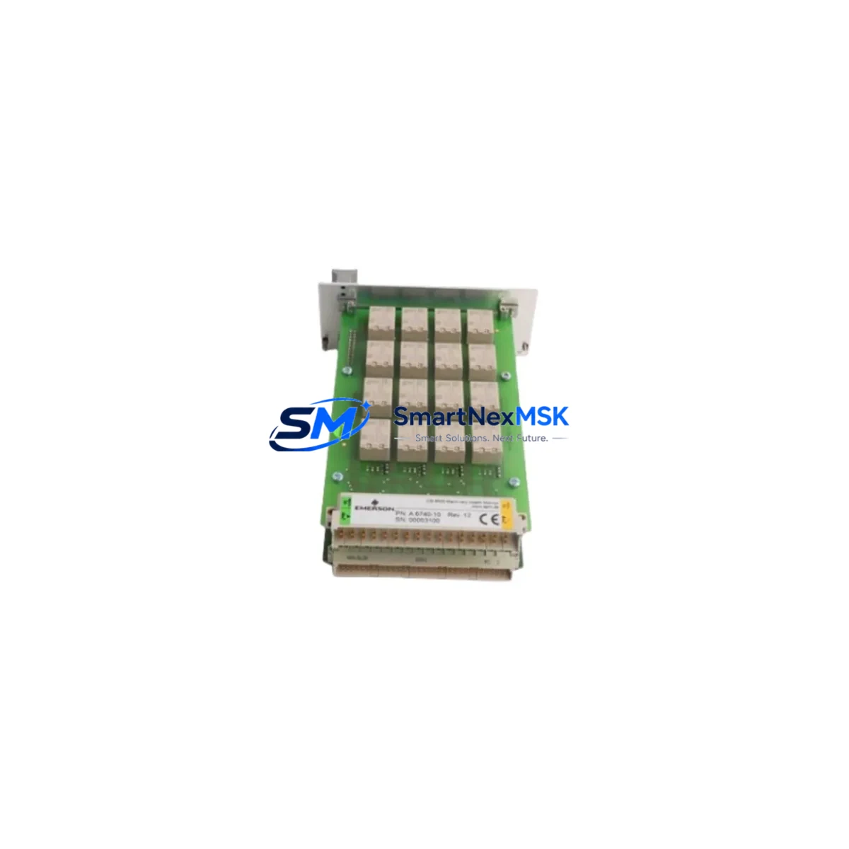
Emerson KJ150X1-BC3 Retrofit-Ready Power Supply for DeltaV Control Systems
The Emerson KJ150X1-BC3 is a field-proven DC power supply module engineered for the DeltaV Series DCS platform. As legacy DeltaV installations age and OEM support windows close, the KJ150X1-BC3 has become one of the most sought-after retrofit components for engineers tasked with modernizing control cabinets without replacing the entire automation architecture. Whether you are restoring a failed power rail, upgrading an aging redundant power configuration, or migrating from an end-of-life predecessor module, the KJ150X1-BC3 delivers the electrical compatibility and mechanical fit required for a smooth, low-risk transition.
This module is designed to slot directly into the standard DeltaV carrier and backplane assembly, maintaining the same terminal block layout and DC bus interface as earlier-generation Emerson power supply units. Engineers replacing discontinued modules such as the KJ150X1-BC1 or KJ150X1-BC2 will find that the BC3 revision preserves backward compatibility at the wiring level, eliminating the need to re-terminate field cables or modify cabinet layouts. The 24 VDC output rail is fully compatible with downstream DeltaV I/O modules including the KJ3001X1-BA1 analog input card, KJ2201X1-BA1 digital output module, and KJ1501X1-BA1 controller interface — all of which draw regulated power from the same backplane bus.
For sites running redundant power configurations, the KJ150X1-BC3 supports hot-standby pairing with a second supply on the same carrier. During a retrofit, it is critical to verify that the existing carrier — typically the KJ149X1-BA1 or equivalent — is rated for the BC3 revision. Backplane slot addressing does not change between BC-series revisions, which means the DeltaV system controller will recognize the replacement module without requiring a hardware rescan or database modification in DeltaV Explorer.
Upgrade Compatibility Table
| Parameter | KJ150X1-BC3 (This Unit) | Legacy / Predecessor |
|---|---|---|
| Output Voltage | 24 VDC regulated | 24 VDC (BC1 / BC2) |
| Backplane Interface | DeltaV standard carrier slot | Same — direct fit |
| Terminal Wiring | Identical terminal block layout | No re-termination required |
| Communication Protocol | DeltaV internal bus (FOUNDATION Fieldbus compatible infrastructure) | Compatible — no protocol migration needed |
| Redundancy Support | Hot-standby pairing supported | Same carrier pairing logic |
| Installation Requirement | DIN rail / carrier mount, standard DeltaV enclosure | No mechanical modification required |
| Commissioning | No DeltaV database rescan required | Slot address preserved |
| Warranty | 12-Month Warranty — covered from date of shipment | |
Retrofit Planning for Existing Automation Systems
A successful KJ150X1-BC3 retrofit begins well before the module arrives on site. The first step is a power budget audit of the existing DeltaV cabinet. Each I/O carrier draws a defined load from the 24 VDC bus, and the total connected load — including the KJ3001X1-BA1 analog input cards, KJ2201X1-BA1 digital output modules, and any HART multiplexer interfaces — must fall within the BC3’s rated output capacity. If the cabinet has been expanded since original commissioning, the power budget may have drifted beyond the original design margin, making this verification non-negotiable before energizing the replacement unit.
Terminal block inspection is the next critical checkpoint. Although the KJ150X1-BC3 uses the same wiring layout as its predecessors, field cables should be inspected for insulation degradation, loose ferrules, and correct torque on terminal screws. In older installations, the AC input wiring to the power supply — typically routed from a dedicated 120 VAC or 240 VAC branch circuit — should be verified against the module’s input voltage selector or auto-ranging specification.
For sites that have integrated FOUNDATION Fieldbus segments or PROFIBUS DP networks into the DeltaV architecture, the power supply retrofit does not affect the fieldbus segment power conditioners, which are independently powered. However, if the cabinet also houses a DeltaV Wireless Gateway or a serial communications module such as the KJ3232X1-BA1 HART interface, these devices should be powered down in a controlled sequence before the supply is swapped to avoid unexpected resets on the communications bus.
HMI continuity is another consideration. DeltaV Operate workstations connected via the DeltaV Application Station will continue to display live process data as long as the controller — typically a KJ3001X1-BA1 or MD-series controller — remains powered through a separate supply or UPS. Planning the swap during a scheduled maintenance window, with the HMI operator informed of the brief power interruption on the affected carrier, is the recommended approach. After reinsertion of the KJ150X1-BC3, the DeltaV system will perform an automatic module health check, and the green status LED on the module confirms successful initialization.
Downtime Control During System Migration
Minimizing unplanned downtime during a DeltaV power supply replacement requires a structured pre-swap checklist. Before removing the failed or end-of-life KJ150X1-BC2 or BC1 unit, export the current DeltaV configuration database and confirm that a recent backup of the controller program — including all function block diagrams, sequential function charts, and alarm configurations — is stored on the DeltaV Application Station or an offline engineering workstation.
If the cabinet operates in a redundant power configuration, the standby supply can absorb the full load while the primary is replaced, reducing the live-circuit swap to a hot-swap operation with zero process interruption. For non-redundant configurations, coordinate with the process team to identify a safe hold state for the controlled process, place the relevant DeltaV controllers in manual mode via DeltaV Operate, and proceed with the swap. The KJ150X1-BC3’s fast startup sequence — typically under 10 seconds from power application to stable output — means the I/O modules and controller will resume normal scan cycles almost immediately after the new supply is seated and latched.
Post-swap verification should include a check of all module status indicators on the DeltaV carrier, a review of the DeltaV Event Chronicle for any fault codes generated during the transition, and a functional test of critical I/O loops before returning the process to automatic control. All units shipped by SMARTNEXMSK are pre-tested under load prior to dispatch, reducing the risk of DOA failures and shortening on-site commissioning time.
Retrofit Support FAQ
Q1: Is the KJ150X1-BC3 a direct drop-in replacement for the KJ150X1-BC1 and KJ150X1-BC2?
Yes. The BC3 revision maintains the same mechanical form factor, terminal block layout, and backplane connector as the BC1 and BC2. No wiring changes or carrier modifications are required. The DeltaV system will recognize the module in the same slot address without a database update.
Q2: What commissioning steps are required after installation?
After seating the KJ150X1-BC3 and restoring AC input power, verify the green status LED on the module front panel. In DeltaV Explorer, confirm the module appears online in the hardware tree. Run a loop check on at least one analog input and one digital output channel on the affected carrier to confirm the 24 VDC bus is stable. No firmware download or module configuration is required for a like-for-like replacement.
Q3: Can this module be used in a redundant power supply configuration?
Yes. The KJ150X1-BC3 supports hot-standby redundancy when paired with a second unit on the same DeltaV carrier. Both modules must be the same revision for the redundancy logic to function correctly. Verify that the carrier’s redundancy jumper or configuration switch is set appropriately before energizing the pair.
Q4: What warranty and testing does SMARTNEXMSK provide?
All KJ150X1-BC3 units are covered by a 12-month warranty from the date of shipment. Each unit undergoes pre-shipment functional testing under load to verify output voltage stability, inrush current behavior, and status indicator operation. A test report is available upon request. Expedited shipping options are available for emergency breakdown situations.
© 2026 SMARTNEXMSK. All rights reserved.
Original Source: https://smartnexmsk.com
Contact: [email protected] | +86 18259474341