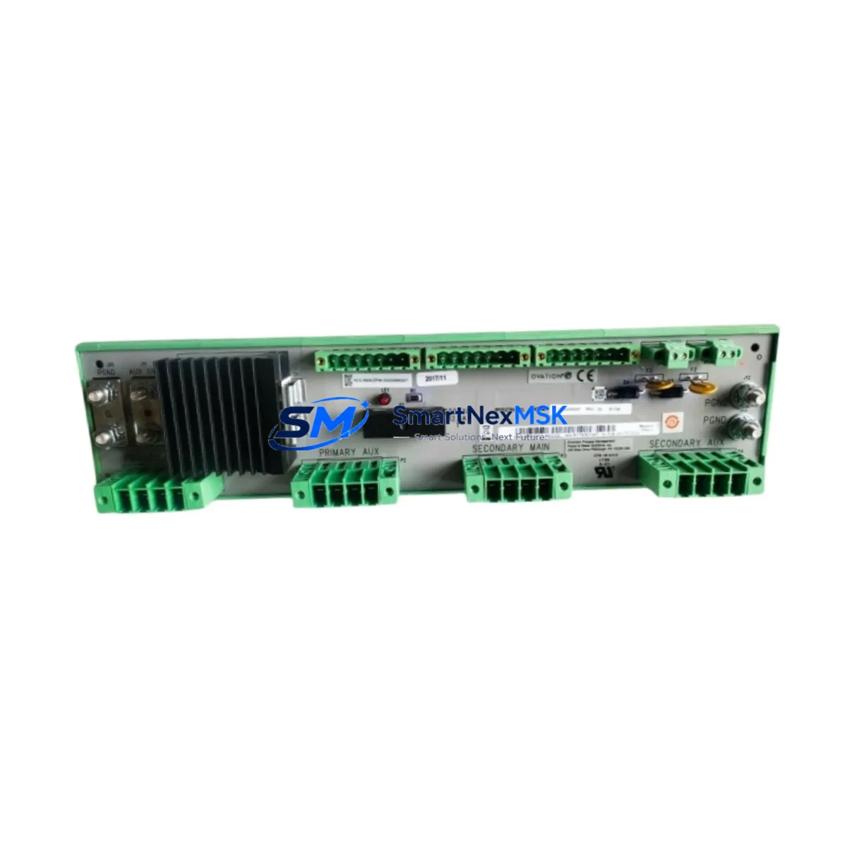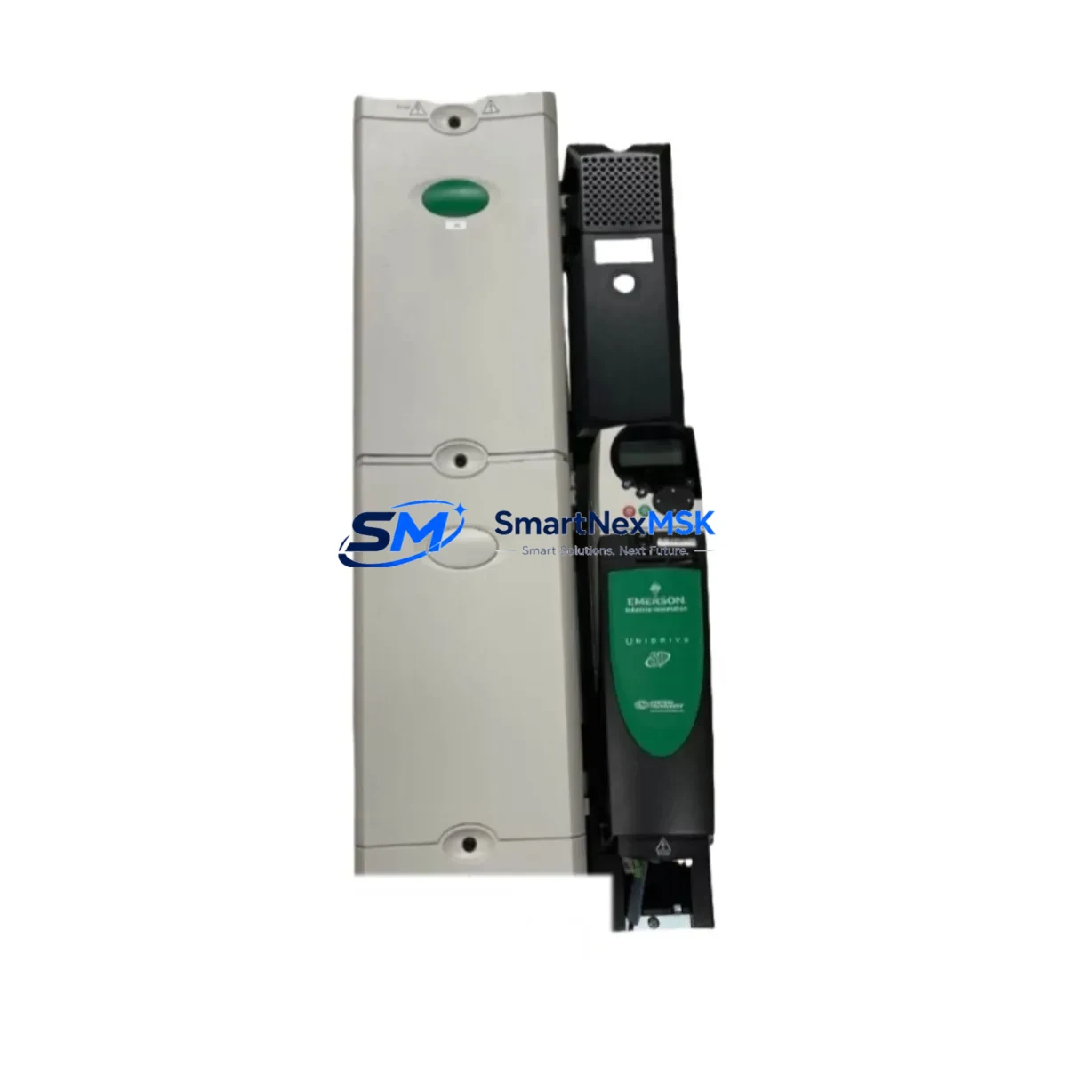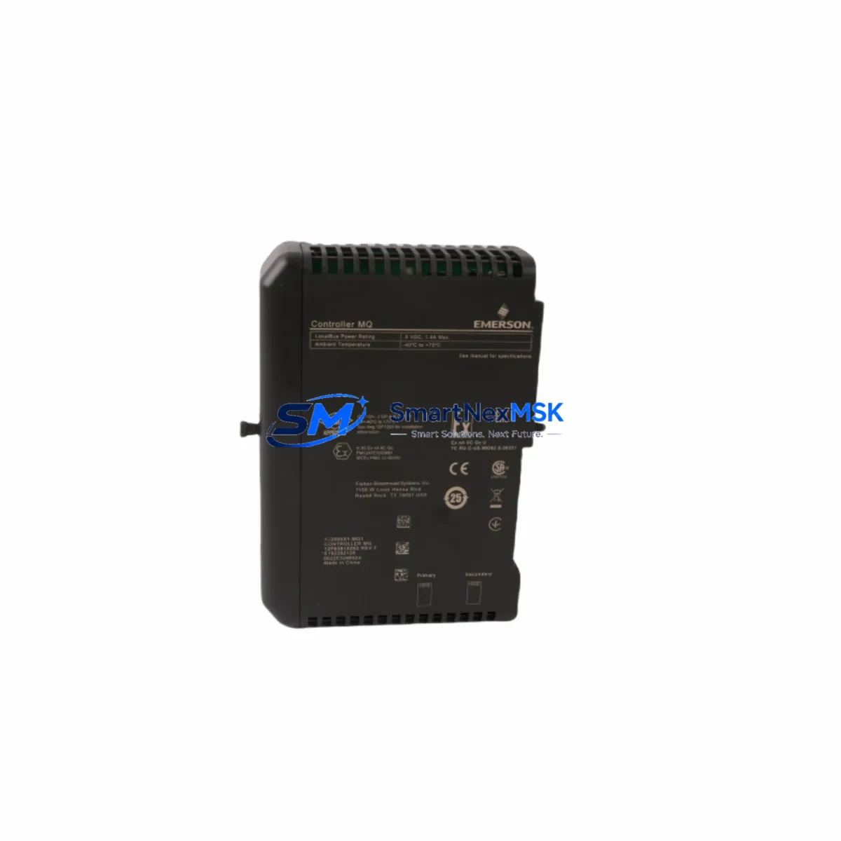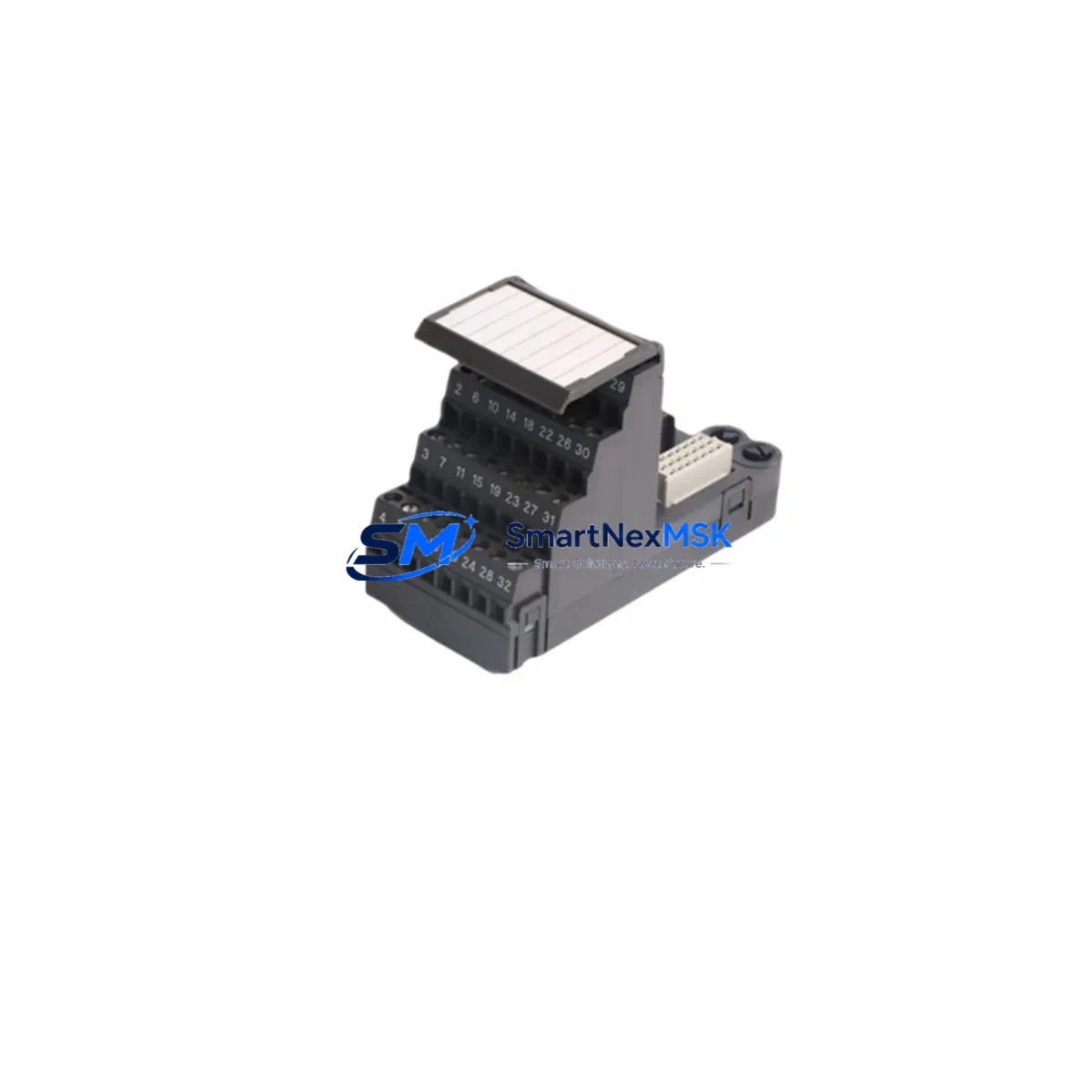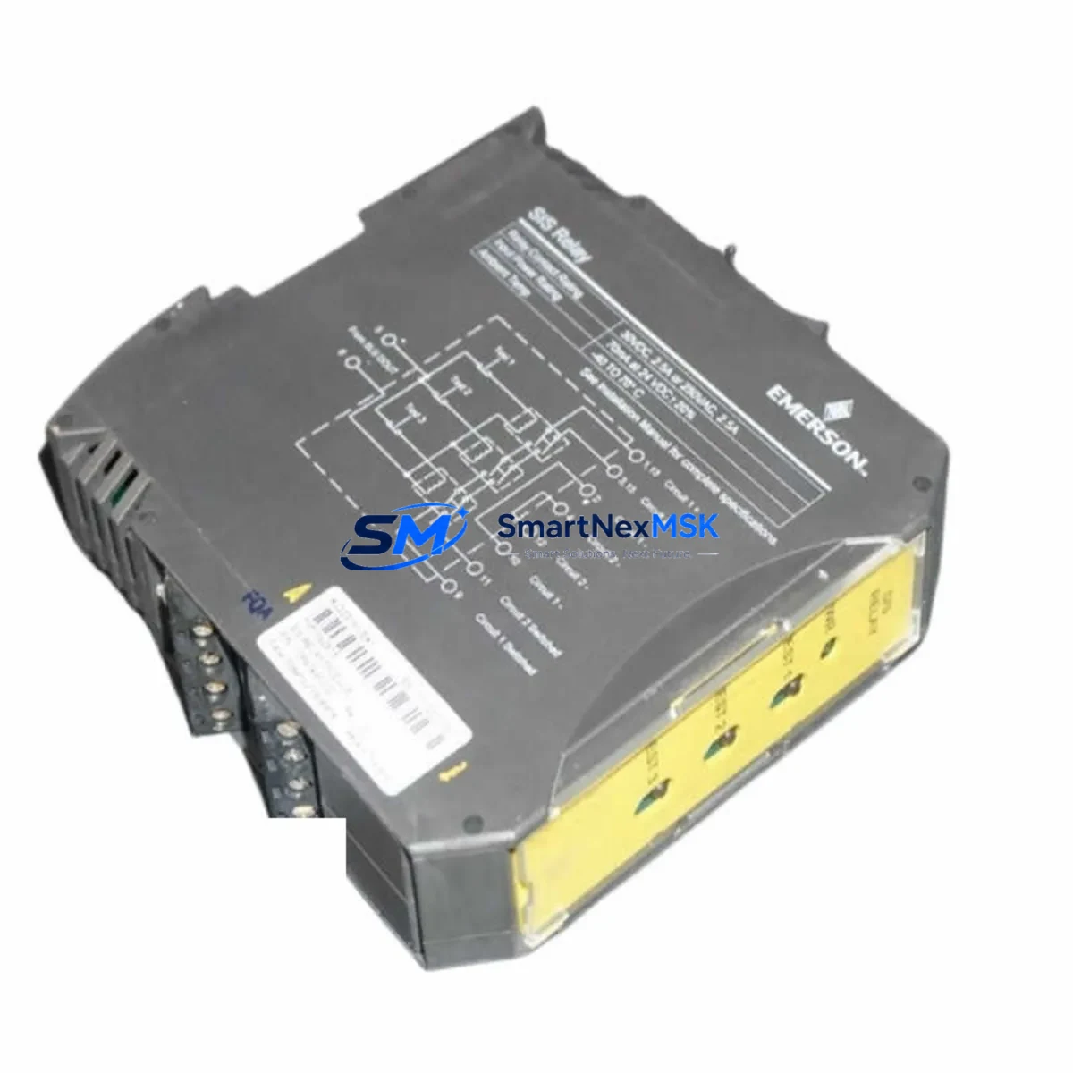
Emerson KJ2231X1-EA1 Retrofit-Ready Relay Output for DeltaV Control Systems
The Emerson KJ2231X1-EA1 is a relay output module engineered for the DeltaV distributed control system platform. As legacy DeltaV installations age and original spare parts become increasingly difficult to source, the KJ2231X1-EA1 serves as a verified retrofit-ready replacement that enables plant engineers to extend the operational life of existing control architectures without committing to a full system overhaul. Whether you are managing a refinery, chemical plant, pharmaceutical batch process, or power generation facility, this module provides the relay switching capacity and backplane compatibility required to maintain continuous process control with minimal disruption.
The KJ2231X1-EA1 is designed to seat directly into the DeltaV S-series carrier and communicate over the standard DeltaV backplane bus. Before installation, engineers should confirm that the target carrier — typically a DeltaV 8-channel or 4-channel I/O carrier — is mechanically and electrically compatible with the relay output module form factor. The module draws power from the carrier’s internal bus, so verifying that the DeltaV power supply module, such as the KJ1501X1-BA2 or equivalent redundant power supply, can sustain the additional load is a critical pre-installation step. Insufficient power headroom is one of the most common causes of unexpected module faults during retrofit commissioning.
Terminal wiring is another area that demands careful attention during a KJ2231X1-EA1 retrofit. Field wiring connected to the outgoing relay contacts must be mapped against the original I/O assignment in the DeltaV Explorer configuration database. If the replacement module is installed in a slot previously occupied by a different output module type — for example, a KJ3002X1-BA1 analog output module — the channel addressing and signal type definitions in the DeltaV controller must be updated accordingly. Failure to realign the module address and I/O tag assignments will result in incorrect control outputs and potential process upsets.
Upgrade Compatibility Table
| Parameter | Details |
|---|---|
| Compatible Platform | Emerson DeltaV S-series DCS |
| Module Type | Relay Output Module |
| Backplane Interface | DeltaV S-series I/O carrier backplane |
| Installation Requirement | DeltaV S-series 8-ch or 4-ch I/O carrier; no hardware modification required |
| Communication Compatibility | DeltaV internal I/O bus; compatible with MD, MD Plus, and MQ controllers |
| Replacement Recommendation | Direct replacement for KJ2231X1-EA1 and functionally equivalent relay output variants |
| Commissioning Focus | I/O tag reassignment in DeltaV Explorer, relay contact wiring verification, power budget check |
| Warranty | 12-Month Warranty — covers manufacturing defects and functional failure under normal operating conditions |
Retrofit Planning for Existing Automation Systems
A successful KJ2231X1-EA1 retrofit begins well before the module arrives on site. The engineering team should pull the current DeltaV system configuration backup and identify every I/O tag assigned to the target slot. In multi-controller DeltaV architectures, the KJ2231X1-EA1 may be installed in a remote I/O enclosure connected to the main controller via a DeltaV CIOC (Controller I/O Card) or through a CHARM I/O architecture using a CHARMS I/O card and associated CHARM baseplates. Understanding the exact I/O topology — whether traditional S-series carrier-based or CHARM-based — determines the correct replacement path and any firmware considerations.
For plants running older DeltaV versions (v10 or earlier), it is advisable to verify that the DeltaV controller firmware supports the KJ2231X1-EA1 module descriptor. The module descriptor file governs how the DeltaV system recognizes and communicates with the relay output module. If the descriptor is absent from the controller’s module library, it must be imported before the module can be commissioned online. This step is often overlooked during rapid maintenance replacements and can extend unplanned downtime significantly.
In control cabinets where the KJ2231X1-EA1 shares a rack with other I/O modules — such as a KJ2201X1-HA1 discrete input module, a KJ3002X1-BA1 analog output module, or a KJ4001X1-EA1 thermocouple input module — the overall rack power consumption must be recalculated after any module swap. The DeltaV power supply module feeding the carrier must be confirmed to have sufficient capacity. Where redundant power is configured using dual KJ1501X1-BA2 power supply modules, both supplies should be load-tested after the retrofit to confirm balanced operation.
HMI faceplates and DeltaV Operate graphics linked to the relay output channels should be reviewed after the module replacement. If the channel count or relay contact configuration differs from the previous module, operators may encounter alarm floods or incorrect status indications on the DeltaV Operate workstation. Updating the graphic display and alarm limits in DeltaV Operate before returning the loop to automatic control prevents operator confusion during the post-retrofit startup phase.
Communication link integrity between the DeltaV controller and the I/O subsystem should be verified using the DeltaV Diagnostics tool after the KJ2231X1-EA1 is seated and powered. Any communication errors logged against the module’s carrier slot indicate either a seating issue, a backplane fault, or a firmware mismatch. In PROFIBUS or FOUNDATION Fieldbus segments connected through a DeltaV PROFIBUS interface card or a DeltaV Fieldbus interface module, the relay output module’s role in the segment addressing scheme must also be confirmed to avoid address conflicts.
Downtime Control During System Migration
Minimizing downtime during a KJ2231X1-EA1 replacement requires a structured hot-swap or cold-swap procedure depending on the DeltaV system’s redundancy configuration. In systems where the relay output module’s carrier supports online module replacement, the DeltaV controller can be placed in a controlled state that holds the last known output values while the module is physically swapped. This output-hold strategy protects the process from unexpected relay state changes during the brief period when the module is unseated.
Before unseating the KJ2231X1-EA1, the field devices connected to the relay contacts — motor starters, solenoid valves, or interlock circuits — should be placed in a safe manual state by the field operator. The DeltaV controller’s module parameter download should be prepared in advance so that once the replacement module is seated and recognized by the system, the full parameter set can be downloaded in a single operation without requiring a controller restart. This approach typically reduces the active swap window to under 15 minutes for a single-module replacement in a well-prepared DeltaV environment.
For plants without online replacement capability, a planned shutdown window should be scheduled during a low-production period. The original program logic stored in the DeltaV controller is preserved on the controller’s internal memory and is not affected by the I/O module swap, provided the controller itself remains powered throughout the procedure. After the new KJ2231X1-EA1 is installed and commissioned, a full I/O checkout — verifying each relay contact against its field device — should be completed before the loop is returned to automatic control. All checkout results should be documented in the plant’s maintenance management system to support future audit and compliance requirements.
Retrofit Support FAQ
Q: Is the KJ2231X1-EA1 a direct drop-in replacement for the original module in my DeltaV S-series system?
A: Yes. The KJ2231X1-EA1 is designed to seat into the standard DeltaV S-series I/O carrier without hardware modification. The module uses the same backplane connector and I/O bus protocol as the original. You will need to confirm that the module descriptor is present in your DeltaV controller’s module library and that the I/O tag assignments in DeltaV Explorer match the relay channel configuration of the replacement module before downloading parameters.
Q: What wiring checks are required before installing the KJ2231X1-EA1?
A: Verify that all field wiring connected to the relay output terminals is de-energized before unseating the original module. Confirm terminal assignments against the original loop drawings and the DeltaV I/O assignment database. Check that relay contact ratings (voltage and current) are compatible with the connected field devices. If the carrier’s terminal block was previously wired for a different module type, re-verify the terminal numbering against the KJ2231X1-EA1 wiring diagram before re-energizing.
Q: How do I verify communication between the KJ2231X1-EA1 and the DeltaV controller after installation?
A: After seating the module and applying power, open DeltaV Diagnostics and navigate to the I/O carrier slot where the module is installed. The module should appear as “Commissioned” with no active communication faults. If the module shows a “Not Commissioned” or “Communication Error” status, check the module seating, verify the carrier power supply output, and confirm that the module descriptor version is compatible with the installed DeltaV controller firmware version.
Q: What does the 12-month warranty cover, and how is it processed?
A: The 12-month warranty covers manufacturing defects and functional failures under normal operating conditions from the date of shipment. Each KJ2231X1-EA1 unit is function-tested prior to dispatch. If a warranty claim is required, contact our sales team with the order reference and a description of the fault. We will arrange a replacement or repair at no additional cost within the warranty period. Warranty does not cover damage resulting from incorrect installation, overvoltage, or physical mishandling.
© 2026 SMARTNEXMSK. All rights reserved.
Original Source: https://smartnexmsk.com
Contact: [email protected] | +86 18259474341