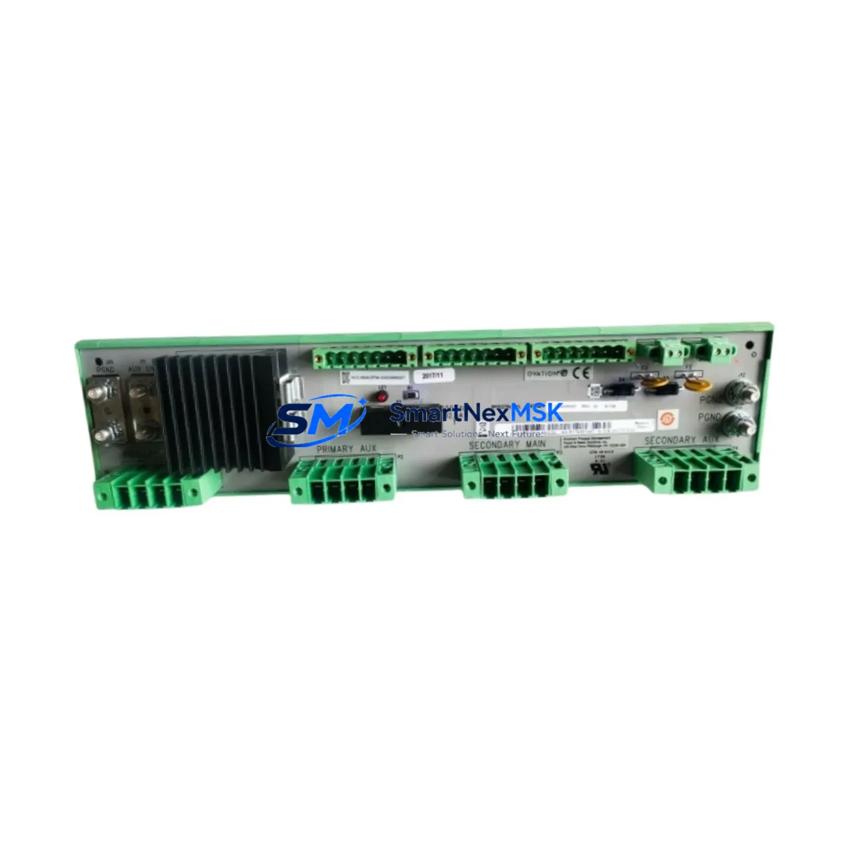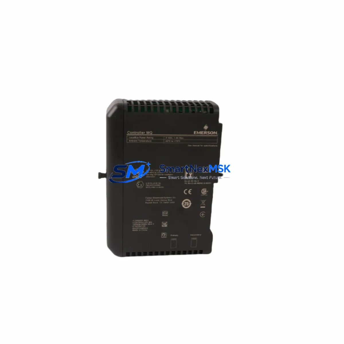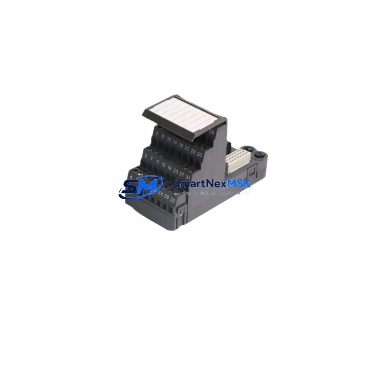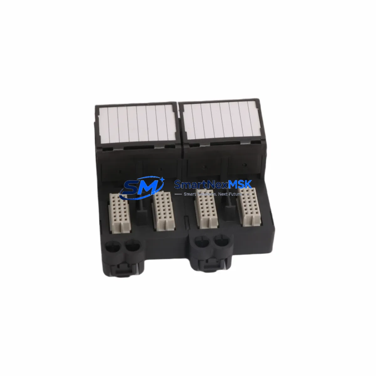
Emerson KJ3241X1-EA1 12P2565X052 Retrofit-Ready Interface Terminal Block for DeltaV S-Series Control Systems
The Emerson KJ3241X1-EA1 (Part No. 12P2565X052) is a retrofit-ready Interface Terminal Block engineered for seamless integration into Emerson DeltaV S-Series distributed control systems. Whether you are replacing a discontinued component, upgrading an aging control cabinet, or restoring a production line after an unplanned failure, this terminal block delivers the electrical compatibility, mechanical fit, and signal integrity required for mission-critical industrial automation environments.
Designed as a direct replacement for legacy DeltaV field interface assemblies, the KJ3241X1-EA1 supports the standard 12-channel I/O wiring architecture used across DeltaV S-Series controller nodes. Its robust screw-terminal design accommodates field wiring from legacy installations without requiring cable re-termination, significantly reducing retrofit labor time and the risk of wiring errors during changeover.
This component is widely deployed in oil and gas, chemical processing, power generation, and pharmaceutical manufacturing facilities where DeltaV S-Series controllers — including the DeltaV MD Plus Controller and DeltaV SD Plus Controller — remain the backbone of process automation. When paired with compatible I/O cards such as the KJ3002X1-BA1 (AI card) or KJ3221X1-BA1 (DI card), the KJ3241X1-EA1 restores full channel functionality without requiring firmware changes or DeltaV configuration updates.
Upgrade Compatibility Table
| Parameter | Details |
|---|---|
| SKU / Part Number | KJ3241X1-EA1 / 12P2565X052 |
| Compatible Platform | Emerson DeltaV S-Series DCS |
| Compatible Controllers | DeltaV MD Plus, SD Plus, MD Controller |
| Interface Type | Interface Terminal Block (ITB), 12-channel |
| Mounting | DeltaV S-Series I/O sub-system carrier / backplane |
| Wiring Compatibility | Direct field-wire termination; no re-termination required for legacy wiring |
| Communication Compatibility | Compatible with DeltaV FOUNDATION Fieldbus H1, HART, and conventional I/O signal paths |
| Replacement Recommendation | Drop-in replacement for discontinued KJ3241X1-EA1 variants; verify backplane slot assignment before installation |
| Commissioning Notes | Confirm module address in DeltaV Explorer; verify channel assignments match existing I/O list; perform loop check before returning to service |
| Warranty | 12 Months from date of shipment |
Retrofit Planning for Existing Automation Systems
A successful retrofit begins well before the replacement component arrives on site. When planning a KJ3241X1-EA1 swap in an operating DeltaV S-Series system, engineers should first audit the existing DeltaV S-Series I/O carrier and confirm that the backplane slot is mechanically and electrically compatible with the replacement unit. The carrier’s bus connector pins should be inspected for corrosion or mechanical damage, particularly in installations that have been in service for more than ten years.
Power budget verification is a critical pre-installation step. The DeltaV S-Series power supply — typically a KJ1501X1-BG2 or equivalent redundant power module — must have sufficient headroom to support the replacement ITB alongside all other active I/O modules in the same carrier. Document the current draw of each installed module before proceeding.
Field wiring should be photographed and labeled before disconnection. The KJ3241X1-EA1 uses a standard 12-terminal screw block layout; however, terminal numbering conventions may differ between legacy and current-generation ITBs. Cross-reference the existing loop drawings against the replacement unit’s terminal assignment diagram to avoid signal inversion or ground faults.
For systems integrating HART-enabled field instruments, confirm that the associated I/O card — such as the KJ3002X1-BA1 Analog Input card — retains its HART pass-through configuration after the ITB swap. HART communication parameters are stored in the DeltaV database, not in the ITB itself, so no re-configuration is typically required. However, a HART communication test using a 375 Field Communicator or equivalent handheld device is recommended after installation.
In control cabinets where the DeltaV system shares enclosure space with third-party PLCs or relay logic panels, verify that the replacement ITB does not introduce ground loop issues. Proper shielding termination at the DeltaV marshalling cabinet is essential. If the existing installation uses a DeltaV CHARM I/O architecture in parallel with the S-Series subsystem, ensure that the field signal routing is not inadvertently duplicated during the retrofit.
For sites migrating from legacy DeltaV S-Series to the newer DeltaV Mx Controller platform, the KJ3241X1-EA1 can serve as an interim solution to maintain production continuity while the migration project is phased in. This approach allows individual control loops to be migrated one at a time, minimizing the scope of any single maintenance window. During this transition, the DeltaV Simulate environment should be used to validate program logic changes before they are downloaded to the live controller.
Downtime Control During System Migration
Minimizing unplanned downtime is the primary concern for any DeltaV S-Series retrofit. The KJ3241X1-EA1 is designed to support a hot-swap-style replacement procedure within the DeltaV S-Series architecture, provided the system is placed in the appropriate maintenance mode before the ITB is removed. Operators should confirm that all affected control loops are in manual mode and that any interlock logic dependent on the channels served by the ITB is temporarily bypassed or acknowledged in the safety system.
Before removing the legacy ITB, export the current DeltaV module configuration using DeltaV Diagnostics and save a backup of the controller database. This ensures that if the replacement unit triggers an unexpected fault — such as a module address conflict or a backplane communication error — the system can be restored to its previous state without data loss.
Physical replacement should be performed with the carrier powered where the DeltaV architecture permits live insertion. After seating the KJ3241X1-EA1, monitor the DeltaV Operate HMI for module status alarms. The replacement ITB should appear as a recognized device within 30 seconds of insertion. If the module does not initialize, check the backplane connector seating and verify that the module address has not been reassigned in the DeltaV hardware configuration.
Once the module is online, perform a systematic loop check for each of the 12 channels. Compare live process values against the historian trend for the same channels prior to the swap. Any deviation greater than the instrument’s stated accuracy should be investigated before returning the loops to automatic control. Document the completed loop checks in the site’s maintenance management system and update the as-built drawings to reflect the replacement.
Total planned downtime for a single KJ3241X1-EA1 replacement in a well-prepared DeltaV S-Series system is typically under two hours, including pre-work, physical swap, loop checks, and return-to-service documentation.
Retrofit Support FAQ
Q1: Is the KJ3241X1-EA1 12P2565X052 a direct drop-in replacement for the original Emerson part?
Yes. The KJ3241X1-EA1 (12P2565X052) is manufactured to the original Emerson specification and is a direct mechanical and electrical replacement for the same part number. No modifications to the DeltaV hardware configuration or field wiring are required in standard S-Series installations. Verify the backplane slot assignment and module address in DeltaV Explorer before installation.
Q2: What commissioning steps are required after installing the replacement ITB?
After physical installation, confirm the module appears as active in DeltaV Diagnostics. Perform a 12-channel loop check, verifying signal continuity and correct engineering unit scaling for each channel. For HART-enabled channels, perform a HART communication test using a compatible handheld communicator. Return all affected loops to automatic control only after all loop checks are documented and signed off.
Q3: How do I verify wiring compatibility between the legacy ITB and the replacement unit?
Compare the terminal assignment diagram of the KJ3241X1-EA1 against the existing loop drawings for your installation. The 12-terminal screw block layout is consistent across S-Series ITB generations; however, confirm that terminal numbering and signal polarity match your site’s wiring documentation. Photograph all existing wiring before disconnection and label each conductor with its terminal number.
Q4: What warranty coverage is provided, and what does it include?
All KJ3241X1-EA1 units supplied by SMARTNEXMSK carry a 12-month warranty from the date of shipment. The warranty covers manufacturing defects and functional failures under normal operating conditions. Each unit undergoes pre-shipment functional testing prior to dispatch. Warranty claims are supported by our technical team; contact [email protected] with your order reference and a description of the fault for rapid resolution.
© 2026 SMARTNEXMSK. All rights reserved.
Original Source: https://smartnexmsk.com
Contact: [email protected] | +86 18259474341