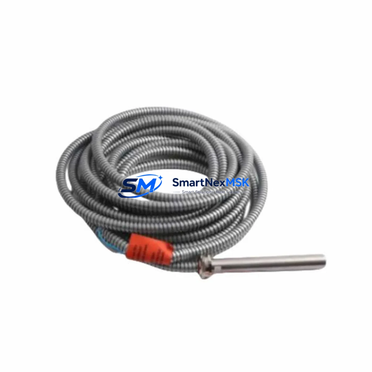
EMERSON PR9376/010-011 Retrofit-Ready Eddy Current Proximity Sensor for Bently Nevada Control Systems
The EMERSON PR9376/010-011 is a high-precision eddy current proximity sensor engineered for seamless compatibility with Bently Nevada vibration monitoring and machinery protection systems. As legacy Bently Nevada sensor assemblies reach end-of-life or become increasingly difficult to source, the PR9376/010-011 provides a verified drop-in retrofit solution that preserves existing wiring, signal conditioning, and monitoring logic without requiring a full system overhaul. Whether you are upgrading a turbine protection panel, replacing a worn shaft-proximity probe in a compressor train, or restoring a critical monitoring loop after an unplanned failure, this sensor delivers the dimensional accuracy, output linearity, and environmental robustness demanded by continuous industrial operation.
Designed to interface directly with Bently Nevada 3300 Series and 3500 Series monitoring racks, the PR9376/010-011 maintains the standard 5 mm or 8 mm tip diameter geometry and outputs a linear voltage signal compatible with existing proximitor extension cables and field wiring. Engineers migrating from earlier Bently Nevada 7200 Series probe assemblies will find that the PR9376/010-011 retains the same sensitivity factor (typically 200 mV/mil or 7.87 V/mm) and gap voltage range, eliminating the need to recalibrate alert and danger setpoints in the monitoring rack. This compatibility significantly reduces commissioning time and minimises the risk of introducing setpoint errors during a live system changeover.
Before installing the PR9376/010-011 into an existing Bently Nevada monitoring loop, engineers should verify several critical parameters. First, confirm that the power supply feeding the proximitor module — typically a Bently Nevada 3300 XL 8mm Proximitor or a 3500/42M Proximitor I/O Module — is within the specified –24 VDC range and that the cable run length between the probe tip and the proximitor does not exceed the qualified extension cable specification. Second, inspect the existing Bently Nevada 330130 or 330180 extension cable connectors for corrosion or mechanical damage; the PR9376/010-011 uses the same standard Bently Nevada connector interface, so reusing existing cables is straightforward provided they pass continuity and insulation resistance checks. Third, verify the target material — typically AISI 4140 or 4340 steel shaft — against the sensor’s calibration curve to ensure the gap voltage at the nominal operating gap (typically 1.0 mm to 2.5 mm) falls within the linear range.
Upgrade Compatibility Table
| Parameter | PR9376/010-011 (This Unit) | Typical Legacy Reference |
|---|---|---|
| Probe Tip Diameter | 8 mm standard | 8 mm (Bently Nevada 330180 series) |
| Sensitivity | 7.87 V/mm (200 mV/mil) | 7.87 V/mm — direct match |
| Supply Voltage | –24 VDC (via proximitor) | –24 VDC — no rewiring required |
| Output Signal | Linear DC voltage | Linear DC voltage — compatible |
| Connector Interface | Standard Bently Nevada MIL-spec | Reuse existing 330130/330180 cables |
| Mounting Thread | M10 × 1 or 3/8–24 UNF (specify) | Same thread — no bracket modification |
| Operating Temperature | –35 °C to +120 °C | Meets or exceeds legacy spec |
| Compatible Rack | Bently Nevada 3300 / 3500 Series | 3300 XL, 3500/42M, 3500/45 |
| Commissioning Requirement | Gap voltage verification only | No setpoint recalibration needed |
| Warranty | 12 Months | — |
Retrofit Planning for Existing Automation Systems
A successful retrofit of the PR9376/010-011 into a running plant begins well before the maintenance window opens. Start by pulling the existing loop drawing to confirm the proximitor model installed in the monitoring rack — common units include the Bently Nevada 3300 XL 8mm Proximitor, the 3500/42M Proximitor I/O Module, and the 3500/45 Position Monitor. Each of these modules accepts the same probe-and-extension-cable assembly, so the PR9376/010-011 integrates without firmware changes or rack reconfiguration.
Next, audit the field wiring. The standard Bently Nevada 330130-045-00-CN or 330180-045-00-CN extension cables connect the probe to the proximitor using a coaxial arrangement; verify that the cable jacket is intact and that the BNC or MIL-C-5015 connector at the proximitor input is free of contamination. If the extension cable is being replaced simultaneously, ensure the total cable length — probe cable plus extension — matches the qualified length for the selected proximitor, typically 5 m, 9 m, or 15 m. Mismatched cable lengths shift the gap voltage curve and can cause nuisance trips or missed alarms on the Bently Nevada 3500 rack.
For plants running a DCS backbone — such as an Emerson DeltaV MD Plus Controller or a Honeywell Experion PKS C300 Controller — the proximity sensor signal is typically hardwired into the Bently Nevada rack and then communicated to the DCS via a Bently Nevada 3500/92 Communication Gateway using Modbus RTU or OPC DA. Confirm that the gateway configuration maps the correct channel address to the new probe after replacement; a channel address mismatch will cause the DCS historian to log data against the wrong asset tag. If the plant uses a Bently Nevada System 1 software platform for machinery diagnostics, update the probe configuration record to reflect the PR9376/010-011 part number and calibration date so that trend data continuity is maintained.
In control cabinets where space is constrained, verify that the PR9376/010-011 body length and armoured cable exit direction are compatible with the existing conduit routing. The sensor ships with a standard 1 m integral cable; if the proximitor is mounted more than 1 m from the probe exit point, a Bently Nevada 330130 extension cable of the appropriate length must be ordered concurrently. Also confirm that the terminal block assignments in the junction box — typically a Pepperl+Fuchs or Phoenix Contact DIN-rail terminal strip — match the coaxial shield grounding convention used by the existing Bently Nevada loop to avoid ground loop interference on the output signal.
Downtime Control During System Migration
Minimising unplanned downtime during a proximity sensor replacement requires a structured hot-swap protocol. Where the process permits a brief bypass, use the Bently Nevada 3500 rack’s built-in channel bypass function to suppress the alarm output for the affected channel before disconnecting the old probe. This prevents a spurious danger trip from propagating to the Emergency Shutdown System (ESD) or the DCS interlock logic while the probe is open-circuit during the swap.
Once the PR9376/010-011 is mechanically installed and the extension cable reconnected, restore the gap voltage to the nominal operating point — typically –10 VDC to –12 VDC at 1.0 mm to 1.5 mm gap — before releasing the channel bypass. Use a calibrated gap-setting tool or a digital multimeter referenced to the proximitor output terminals to confirm the gap voltage is within the linear range before the machine is returned to service. Document the as-found and as-left gap voltages in the maintenance management system to support future trend analysis.
For critical machinery where even a brief bypass is not acceptable — such as a high-speed gas turbine or a boiler feed pump — consider pre-staging a complete spare probe-and-cable assembly, pre-gapped and pre-tested on a bench fixture, so that the field swap time is reduced to the minimum mechanical disconnection and reconnection sequence. The PR9376/010-011 is supplied with a factory test certificate confirming output linearity and sensitivity, which can be used to validate the spare assembly before the maintenance window begins. This approach, combined with a pre-written step-by-step work instruction referencing the Bently Nevada 3500 rack bypass procedure, consistently achieves sensor replacement times of under 30 minutes without compromising the integrity of the machinery protection logic.
After the replacement is complete and the channel bypass is released, monitor the Bently Nevada System 1 or 3500 rack display for at least one full machine start-up cycle to confirm that the vibration and position readings are stable, that no spurious alarms are generated, and that the DCS historian is receiving valid data on the correct asset tag. A final out-of-service functional test — simulating a high-vibration condition by adjusting the probe gap beyond the danger setpoint — verifies that the full protection loop, from sensor through proximitor to rack output relay, is operating correctly before the work order is closed.
Retrofit Support FAQ
Q1: Is the PR9376/010-011 a direct replacement for the Bently Nevada 330180-045-00-CN probe assembly?
Yes. The PR9376/010-011 matches the 8 mm tip diameter, 7.87 V/mm sensitivity, –24 VDC supply, and standard Bently Nevada connector interface of the 330180 series. No setpoint changes are required in the 3300 or 3500 monitoring rack. Confirm the mounting thread specification (M10 × 1 or 3/8–24 UNF) when ordering to ensure mechanical compatibility with the existing probe holder.
Q2: What commissioning checks are required after installation?
Verify the gap voltage at the proximitor output terminals using a digital multimeter. The nominal gap voltage should fall between –10 VDC and –12 VDC at the specified operating gap. Confirm that the Bently Nevada 3500 rack channel is reading within the expected vibration baseline for the machine at rest, and release the channel bypass only after the gap voltage is confirmed. Update the probe record in Bently Nevada System 1 with the new part number and calibration date.
Q3: Can the existing Bently Nevada 330130 extension cable be reused?
Yes, provided the cable passes a visual inspection and a coaxial continuity and insulation resistance test. The PR9376/010-011 uses the same connector interface as the 330130 and 330180 extension cable series. Ensure the total qualified cable length (probe cable + extension) matches the proximitor specification — typically 5 m, 9 m, or 15 m — to maintain calibration accuracy.
Q4: What warranty and pre-shipment testing does the PR9376/010-011 include?
Every PR9376/010-011 unit is supplied with a 12-month warranty covering manufacturing defects and performance deviations from the published specification. Each unit undergoes a factory acceptance test confirming output linearity, sensitivity factor, and insulation resistance before shipment. A factory test certificate is included with each shipment. Units are available from in-stock inventory for immediate dispatch, supporting urgent replacement and unplanned maintenance scenarios.
© 2026 SMARTNEXMSK. All rights reserved.
Original Source: https://smartnexmsk.com
Contact: [email protected] | +86 18259474341