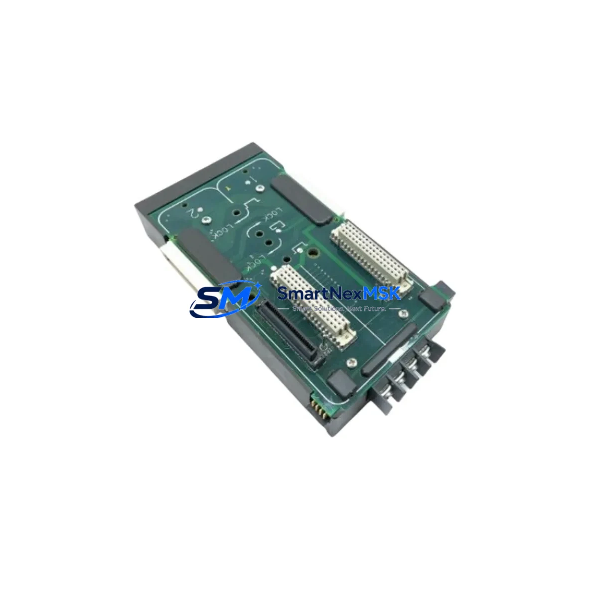
Emerson VE3051C0 KJ4001X1-BA3 Retrofit-Ready Carrier for DeltaV: Compatible Modernization and Smooth System Upgrade
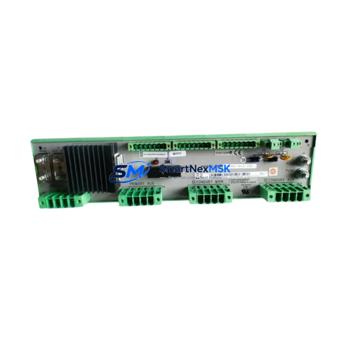
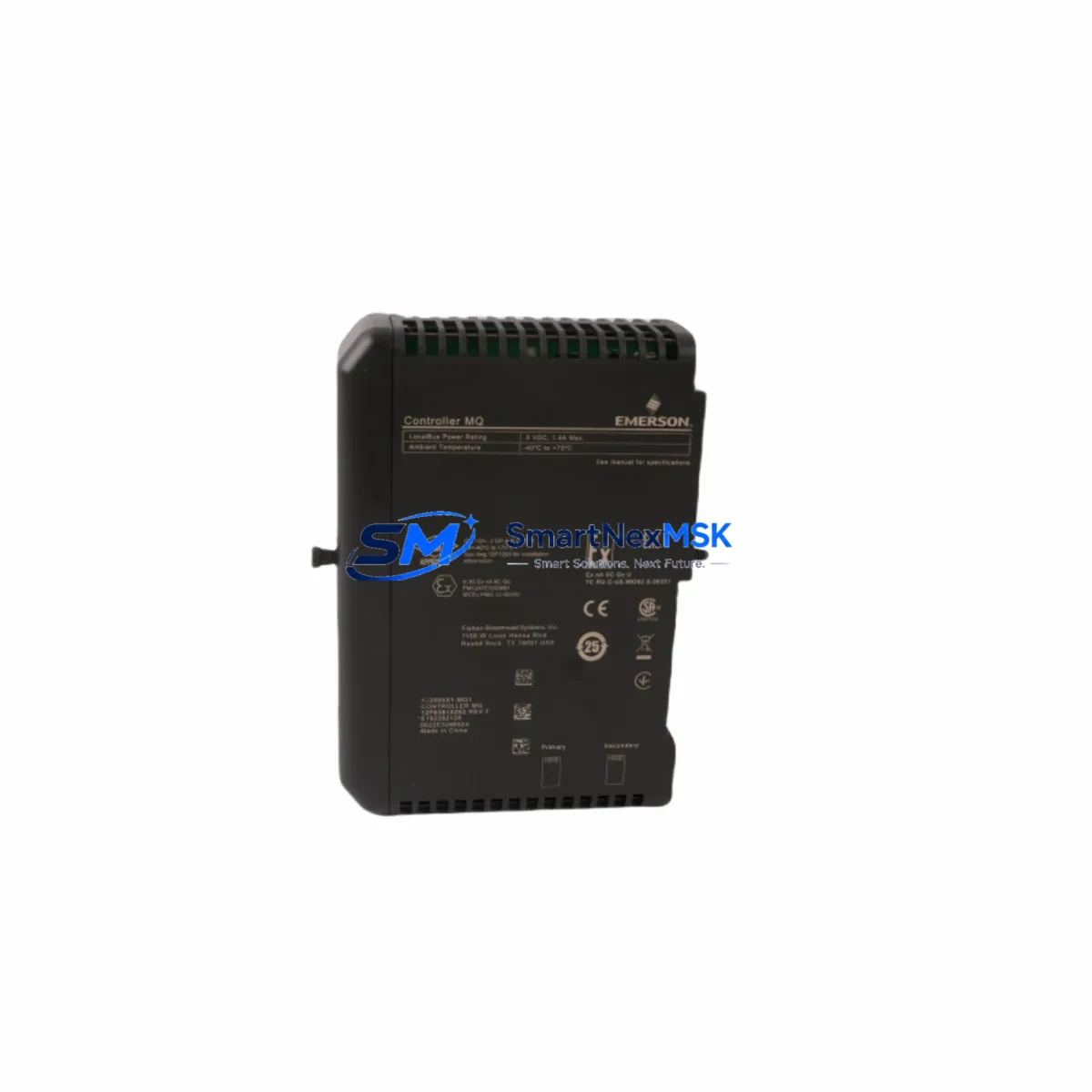
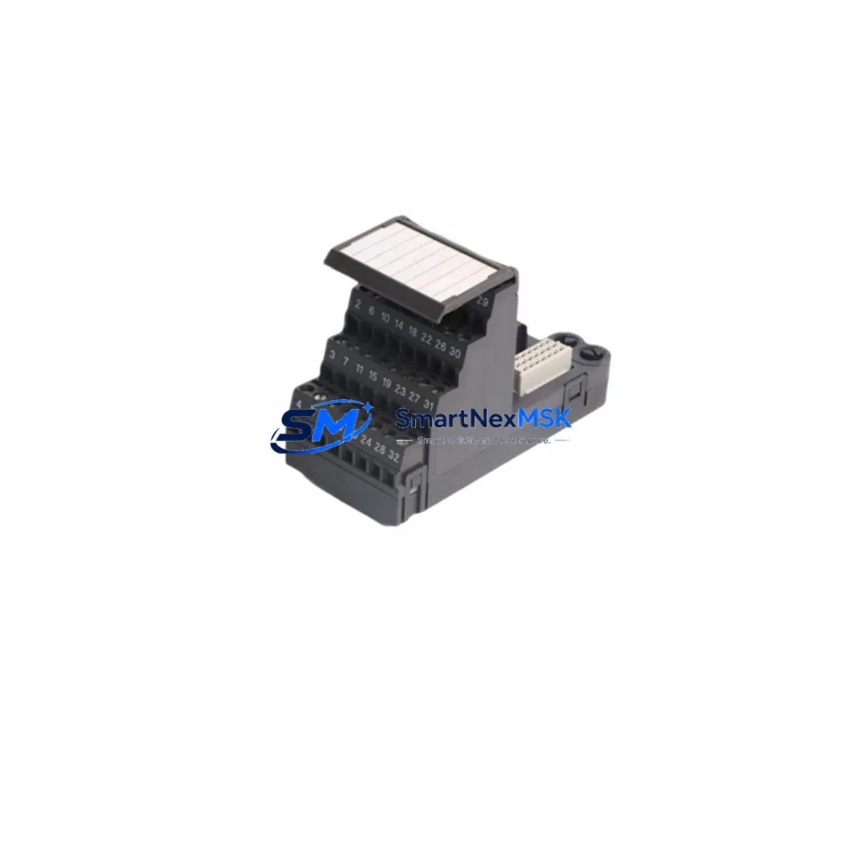
The Emerson VE3051C0 KJ4001X1-BA3 (part number 12P3378X012) is a wide carrier base module designed for the Emerson DeltaV distributed control system platform. As legacy DeltaV installations age and original carrier bases reach end-of-life, this module serves as a direct retrofit replacement, enabling control engineers to restore full I/O capacity without redesigning the control cabinet or rewriting the application program. Whether you are recovering from an unplanned failure, executing a planned upgrade cycle, or expanding an existing DeltaV node, the VE3051C0 KJ4001X1-BA3 provides the mechanical and electrical compatibility required for a low-risk, minimum-downtime swap.
This carrier base accommodates the standard DeltaV I/O module footprint and interfaces directly with the DeltaV controller backplane. It supports the full range of DeltaV Series 2 I/O modules, including analog input cards such as the KJ3002X1-BA1, analog output cards, discrete input and output modules, and HART-enabled field device interfaces. The terminal block wiring layout follows the original DeltaV field wiring standard, meaning existing marshalling panels, junction boxes, and field cable terminations can be retained without modification during the retrofit process.
When planning a retrofit around the VE3051C0 KJ4001X1-BA3, engineers should verify the power budget of the existing DeltaV power supply module — typically a KJ4001X1-BA1 or equivalent — to confirm it can support the full complement of I/O cards installed on the replacement carrier. The carrier draws power from the DeltaV node bus, and any expansion of I/O density during the upgrade must be accounted for in the power margin calculation. In installations where the existing power supply is already near capacity, a parallel power supply or a KJ4001X1-BA2 redundant power module may be required before the new carrier is commissioned.
The backplane interface of the VE3051C0 KJ4001X1-BA3 uses the standard DeltaV node bus connector, which is mechanically keyed to prevent incorrect insertion. Before removing the legacy carrier, technicians should document the module slot assignments, I/O channel-to-tag mappings, and any module-level configuration parameters stored in DeltaV Explorer. The DeltaV controller — whether a KJ2003X1-BA1 MD-Plus or a newer MD Controller — retains the application database independently of the physical carrier hardware, so the control logic, PID tuning parameters, and alarm setpoints are preserved across the hardware swap without requiring a database restore.
Communication link integrity is a critical checkpoint during any DeltaV carrier retrofit. The VE3051C0 KJ4001X1-BA3 does not host a communication processor; the node communication is managed by the DeltaV controller module seated in the designated controller slot of the carrier. After physical installation, the DeltaV system will automatically re-enumerate the I/O modules and re-establish the fieldbus communication links, including HART pass-through to field instruments. If the installation includes a DeltaV SIS Safety Instrumented System node or a CHARM I/O carrier in the same cabinet, those subsystems operate on independent communication paths and are not affected by the carrier replacement.
For sites running HMI graphics built in DeltaV Operate or a third-party SCADA system connected via OPC-DA or OPC-UA, the tag database remains unchanged after the carrier swap, so no HMI screen modifications or OPC server reconfiguration are required. This is a significant advantage over platform migrations that require full tag remapping and HMI redevelopment. The retrofit is transparent to the operator interface layer, which means the control room can remain in service during the physical swap if a hot-standby controller configuration is in place.
Field commissioning after installation of the VE3051C0 KJ4001X1-BA3 should follow the standard DeltaV I/O checkout procedure: confirm module LED status, verify channel-level diagnostics in DeltaV Diagnostics, perform a loop check on critical analog inputs and outputs, and validate discrete I/O states against the field device status. Any HART device descriptors previously loaded into the DeltaV HART Device Library are retained in the controller database and will re-associate automatically with the corresponding I/O channels once the modules are recognized by the system.
Every VE3051C0 KJ4001X1-BA3 unit supplied by SMARTNEXMSK is sourced from verified supply channels, inspected prior to dispatch, and covered by a 12-month warranty against manufacturing defects and functional failure. Units are available from stock for immediate shipment, supporting both emergency breakdown recovery and scheduled maintenance windows. Global logistics are supported, with export documentation available for international shipments.
Upgrade Compatibility Table
| Parameter | Detail |
|---|---|
| Part Number | VE3051C0 / KJ4001X1-BA3 / 12P3378X012 |
| Compatible Platform | Emerson DeltaV Distributed Control System (Series 2) |
| Module Type | Wide Carrier Base Module |
| Backplane Interface | DeltaV Node Bus (standard keyed connector) |
| Supported I/O Modules | DeltaV Series 2 AI, AO, DI, DO, HART I/O cards (e.g. KJ3002X1-BA1) |
| Controller Compatibility | KJ2003X1-BA1 MD-Plus, MD Controller, MD Plus Redundant |
| Power Supply Compatibility | KJ4001X1-BA1, KJ4001X1-BA2 (redundant) |
| Terminal Wiring | Compatible with existing DeltaV field wiring standard; no rewiring required |
| Communication Protocol | DeltaV Node Bus; HART pass-through via I/O modules |
| HMI Impact | None — tag database and OPC server configuration unchanged |
| Installation Method | Direct drop-in replacement; DIN rail or panel mount |
| Retrofit Risk Level | Low — no program rewrite, no tag remapping required |
| Commissioning | DeltaV Diagnostics loop check; HART device auto-association |
| Warranty | 12 Months — covers manufacturing defects and functional failure |
| Availability | In stock — immediate dispatch, global shipping supported |
Retrofit Planning for Existing Automation Systems
A successful retrofit centered on the VE3051C0 KJ4001X1-BA3 begins with a thorough audit of the existing DeltaV node. The first step is to inventory all I/O modules currently seated in the legacy carrier — including any KJ3002X1-BA1 analog input modules, KJ3222X1-BA1 discrete output modules, and KJ3001X1-BA1 analog output cards — and confirm that each module’s firmware revision is compatible with the target DeltaV system version. If the site is also upgrading the DeltaV controller from an older MD Controller to a newer generation, the I/O module firmware may need to be updated before the new carrier is commissioned.
The power supply audit is equally important. The KJ4001X1-BA1 power supply module mounted in the existing node enclosure should be load-tested against the combined power draw of all I/O modules planned for the new carrier. If the node also hosts a DeltaV Wireless I/O Gateway or a PROFIBUS DP interface module, those devices add to the power budget and must be included in the calculation. In high-density nodes where power margin is tight, installing a KJ4001X1-BA2 redundant power supply pair before the carrier swap eliminates the risk of a power-related commissioning failure.
The control cabinet layout should also be reviewed before the carrier is physically replaced. The VE3051C0 KJ4001X1-BA3 wide carrier occupies the same DIN rail footprint as the legacy wide carrier, but cable management around the terminal blocks should be inspected to ensure that existing field cables — including shielded twisted-pair runs from pressure transmitters, thermocouple inputs, and solenoid valve outputs — have sufficient slack to reach the replacement carrier’s terminal positions without stress on the conductors. If the cabinet also contains a DeltaV SIS logic solver or a Rosemount 3051 transmitter wired directly to a HART I/O channel, those connections should be documented and tagged before the swap begins.
For sites that include a DeltaV Batch Executive or a DeltaV Advanced Control application, the retrofit window should be coordinated with the process scheduler to avoid interrupting an active batch sequence or a model predictive control calculation cycle. The DeltaV controller retains all application logic in non-volatile memory, so a controlled power-down of the node during the carrier swap does not result in program loss. After the new carrier is installed and powered, the controller will reload the application and resume execution from the last known state, provided the I/O module slot assignments match the pre-swap configuration stored in DeltaV Explorer.
Downtime Control During System Migration
Minimizing process downtime during a DeltaV carrier retrofit requires a structured pre-swap preparation protocol. Before the maintenance window begins, the control strategy for all loops associated with the affected node should be switched to manual mode at the DeltaV Operate workstation, with the current output values recorded. This ensures that field devices — including control valves, variable frequency drives, and motor starters — remain in a safe, known state during the hardware swap interval.
If the DeltaV node operates in a redundant controller configuration using a pair of KJ2003X1-BA1 MD-Plus controllers, the redundancy switchover mechanism can be used to transfer control to the secondary controller before the primary node is taken offline for the carrier replacement. This approach reduces the effective process interruption to the switchover transient, which is typically less than one scan cycle. The secondary controller continues to execute the application and communicate with the field devices through its own I/O path while the primary carrier is replaced.
After the VE3051C0 KJ4001X1-BA3 is installed and the I/O modules are reseated, the node should be powered up in a controlled sequence: power supply first, then controller, then I/O modules. The DeltaV system will perform an automatic module recognition scan and flag any slot mismatches in the DeltaV Diagnostics display. Once all modules are recognized and channel diagnostics are clear, the control loops can be returned to automatic mode in a staged sequence, starting with the most critical process variables. The total swap time for an experienced technician, including pre-swap preparation and post-swap loop verification, is typically 30 to 90 minutes depending on node density.
All retrofit activities should be documented in the site’s management of change (MOC) record, including the pre-swap module inventory, the post-swap loop check results, and the as-found and as-left wiring photographs. This documentation supports future maintenance planning and provides the evidence base required for functional safety audits in SIL-rated applications.
Retrofit Support FAQ
Q1: Is the VE3051C0 KJ4001X1-BA3 a direct drop-in replacement for the original DeltaV wide carrier base?
Yes. The VE3051C0 KJ4001X1-BA3 uses the same DeltaV node bus backplane connector, the same DIN rail mounting footprint, and the same terminal block wiring layout as the original wide carrier. Existing field wiring, I/O modules, and controller modules can be transferred directly to the replacement carrier without modification. The DeltaV system recognizes the new carrier automatically upon power-up.
Q2: Will my DeltaV application program and tag database be preserved after the carrier swap?
Yes. The DeltaV application database, including all control modules, PID parameters, alarm configurations, and tag definitions, is stored in the DeltaV controller module and in the DeltaV Pro Plus workstation database — not in the carrier base. Replacing the carrier does not affect the application program. After the swap, the controller reloads the application from its non-volatile memory and resumes normal execution once the I/O modules are recognized.
Q3: What wiring and terminal checks should be performed before and after the carrier replacement?
Before removal, photograph the existing terminal block wiring and record the channel-to-tag assignments from DeltaV Explorer. After installation of the VE3051C0 KJ4001X1-BA3, verify that all field cables are correctly terminated at the matching terminal positions, check shield grounding continuity, and perform a channel-level loop check using DeltaV Diagnostics. For HART-enabled channels, confirm that the HART device descriptor is correctly associated in the DeltaV HART Device Library.
Q4: What does the 12-month warranty cover, and what is the dispatch lead time?
Every VE3051C0 KJ4001X1-BA3 unit is covered by a 12-month warranty from the date of dispatch, covering manufacturing defects and functional failure under normal operating conditions. Units are available from stock and are dispatched within 1–2 business days of order confirmation. Pre-shipment functional testing is performed on all units. Export documentation for international shipments is available upon request.
© 2026 SMARTNEXMSK. All rights reserved.
Original Source: https://smartnexmsk.com
Contact: [email protected] | +86 18259474341