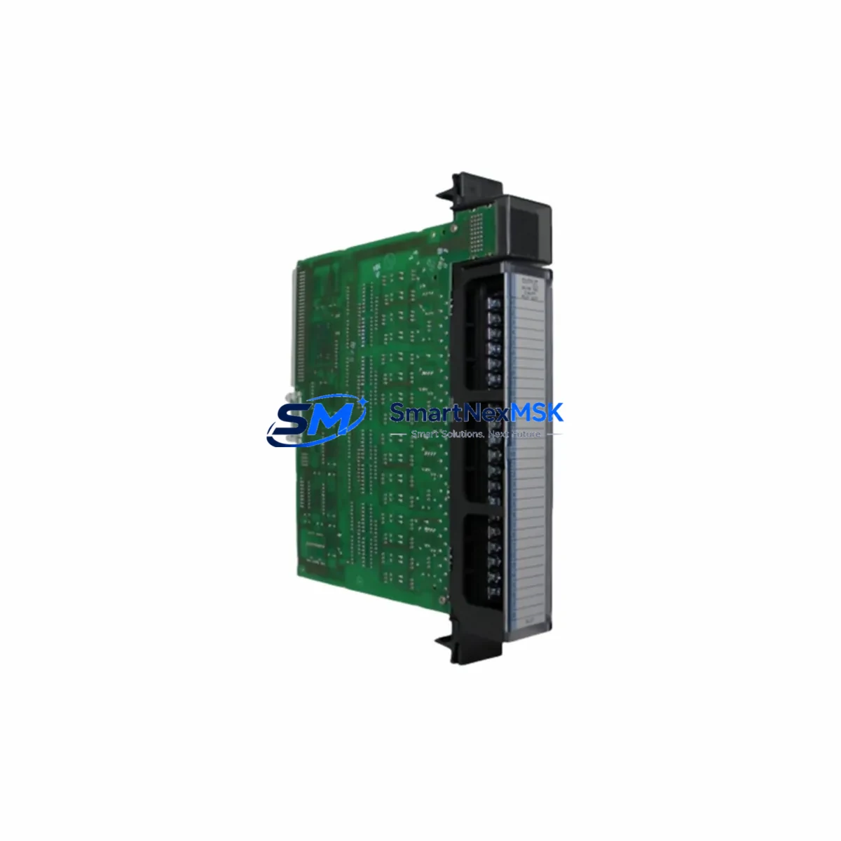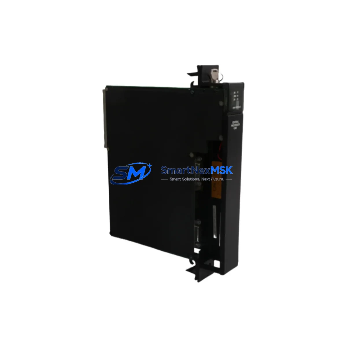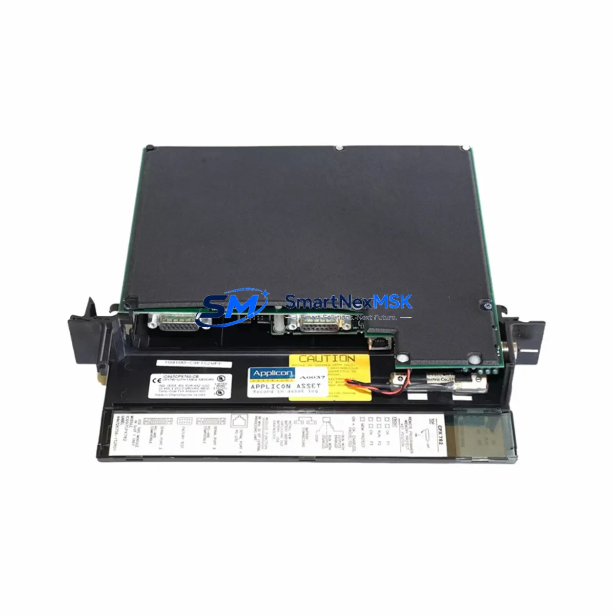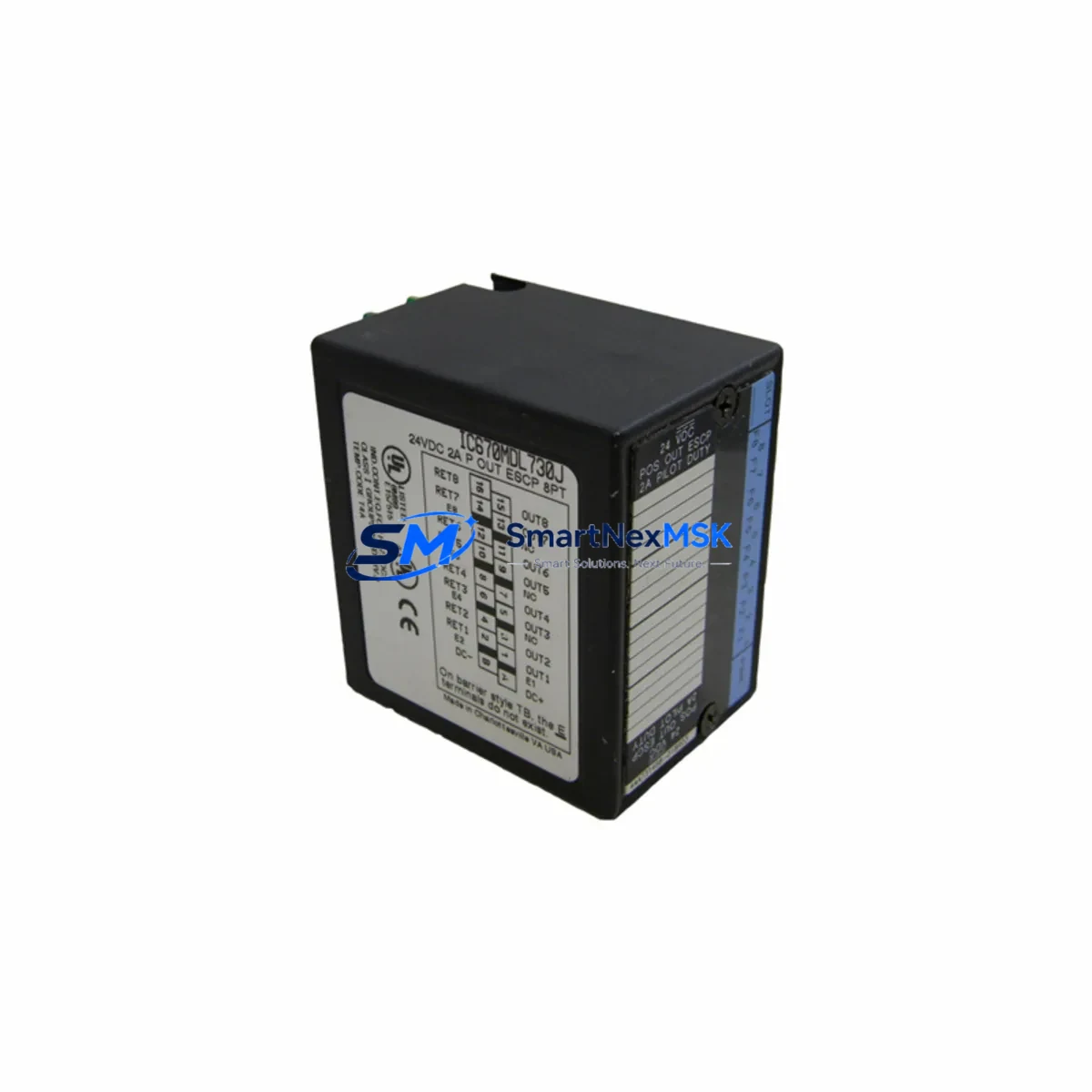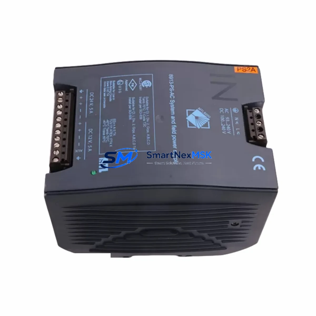
GE 8913-PS-AC Maintenance-Ready Spare for 90-30 Automation
The GE 8913-PS-AC is an original AC input power supply module designed for the GE Series 90-30 programmable logic controller platform — one of the most widely deployed PLC families in North American industrial automation. For maintenance engineers managing aging 90-30 control systems, securing a verified replacement power supply is the single most critical step in any unplanned downtime recovery plan. Power supply failures account for a disproportionate share of PLC-related production stoppages, and the 8913-PS-AC is the direct, form-fit-function replacement that restores system operation without requiring rack reconfiguration or firmware changes.
Whether you are executing a planned annual shutdown inspection, responding to an emergency fault alarm, or building out your site spare parts inventory for long-term system continuity, the 8913-PS-AC delivers the electrical stability and compatibility that Series 90-30 installations demand. Each unit is sourced as an original GE component, functionally tested prior to shipment, and backed by a 12-month warranty — giving procurement engineers the confidence to stock this module as a strategic spare.
Spare Maintenance Table
| Parameter | Specification |
|---|---|
| Part Number / SKU | 8913-PS-AC |
| Brand | GE Automation & Controls |
| Series | GE Series 90-30 |
| Module Type | AC Input Power Supply Module |
| Input Voltage | 120/240 VAC, 47–63 Hz (auto-ranging) |
| Output Voltage | +5 VDC, +24 VDC (backplane regulated) |
| Power Rating | 30W continuous (typical Series 90-30 rack load) |
| Rack Compatibility | IC693CHS391, IC693CHS392, IC693CHS393 (5-slot, 10-slot, expansion) |
| Installation | Slide-in module, left-most slot of 90-30 rack |
| Operating Temperature | 0°C to 60°C (32°F to 140°F) |
| Humidity | 5% to 95% non-condensing |
| Mounting | DIN rail or panel-mount rack |
| Certifications | UL Listed, CE Marked |
| Origin | United States |
| Condition | Original, functionally tested |
| Warranty | 12 Months |
Maintenance Planning for Continuous Operation
A power supply failure in a Series 90-30 rack does not occur in isolation. When the 8913-PS-AC is flagged for replacement during a control cabinet inspection or fault diagnosis, experienced maintenance engineers treat it as a trigger for a broader system health check. The power supply feeds the entire backplane, meaning any marginal voltage output can cause erratic behavior across all installed modules — from CPU modules such as the IC693CPU374 or IC693CPU375 to discrete I/O modules like the IC693MDL645 (16-point 24VDC input) and IC693MDL740 (12-point relay output).
During the replacement procedure, it is standard practice to inspect the IC693CBL001 or IC693CBL316 rack interconnect cables for insulation wear or loose terminations, particularly in high-vibration environments. Analog I/O modules such as the IC693ALG221 (4-channel analog input) should be checked for signal drift that may have been masked by an unstable power rail. If the cabinet includes a communications module — for example the IC693CMM321 for Ethernet or the IC693PCM300 for serial communications — verify that the module re-establishes its network connection cleanly after power restoration, as some firmware versions require a cold-boot cycle.
Terminal blocks and field wiring connections on the I/O side should be torqued to specification and inspected for corrosion, especially in humid or chemically aggressive plant environments. If the system includes a Hand-Held Monitor (HHM) or a Cimplicity HMI workstation connected via the SNP/SNPX port, confirm that the HMI re-synchronizes with the CPU after the power supply swap. For installations using signal isolators between field sensors and the 90-30 analog inputs, verify isolator output levels are within the module’s input range following the power cycle. Fuse holders on the AC input side of the cabinet should also be inspected — a nuisance fuse blow is sometimes the first symptom of a power supply that is beginning to fail.
Stocking the 8913-PS-AC alongside one spare CPU module and at least one spare I/O module per installed type is the recommended minimum spare parts strategy for any facility running Series 90-30 as a primary control platform. This approach ensures that a single-component failure never becomes a multi-day production outage.
Site Replacement Workflow
Step 1 — Fault Confirmation: Use the GE Proficy Machine Edition programming software or the HHM to read the active fault table. Confirm that the fault is power-supply-related (typically a “Power Supply Failure” or “Rack Power Loss” diagnostic) and not a downstream module fault that is presenting as a power issue.
Step 2 — Safe Isolation: Follow your site LOTO (Lockout/Tagout) procedure. Isolate the AC supply to the rack. Allow the backplane capacitors to discharge for a minimum of 30 seconds before handling modules.
Step 3 — Module Removal: The 8913-PS-AC slides into the leftmost position of the 90-30 rack and is secured by a single captive screw. Remove the screw, pull the module handle forward, and slide the unit out of the rack. Note the condition of the backplane connector pins for any signs of arcing or contamination.
Step 4 — Replacement Installation: Insert the new 8913-PS-AC into the same slot. The module is keyed and cannot be installed in the wrong orientation. Tighten the captive screw to the specified torque. Reconnect the AC input wiring to the terminal block on the front of the module, observing correct L1, L2/N, and PE connections.
Step 5 — Power-Up and Verification: Restore AC power. Observe the module status LEDs — the green POWER LED should illuminate within 2 seconds. The CPU should transition from STOP to RUN mode automatically if configured to do so. Clear the fault table and verify all I/O modules report healthy status. Confirm field device operation before releasing the system to production.
This workflow is compatible with all Series 90-30 rack configurations and does not require any software changes, parameter re-entry, or CPU re-programming. The 8913-PS-AC is a direct drop-in replacement for all prior revisions of the same part number.
Spare Parts Support FAQ
Q1: Is the 8913-PS-AC compatible with all Series 90-30 rack sizes?
Yes. The 8913-PS-AC is compatible with all standard Series 90-30 rack configurations, including the 5-slot (IC693CHS391), 10-slot (IC693CHS392), and expansion racks (IC693CHS393). It is the universal AC power supply for the 90-30 platform and does not require any rack-specific configuration.
Q2: How is the unit tested before shipment?
Each 8913-PS-AC unit undergoes functional power-on testing to verify output voltage regulation on both the +5 VDC and +24 VDC rails before dispatch. Units that do not meet GE’s original output specifications are not shipped. A test report is available upon request for critical infrastructure procurement.
Q3: What is the recommended spare parts stocking strategy for Series 90-30 sites?
For facilities with 3 or more Series 90-30 racks in service, we recommend maintaining a minimum of 2 units of the 8913-PS-AC in on-site inventory. Power supplies are wear items with a finite service life, and having an immediate replacement available eliminates the lead-time risk during an unplanned outage. Pair this with a spare CPU module and representative I/O spares for a complete first-response kit.
Q4: What does the 12-month warranty cover?
The 12-month warranty covers all manufacturing defects and functional failures under normal operating conditions. If a unit fails within the warranty period, we provide a replacement or full refund. The warranty period begins from the date of shipment. Warranty claims are processed within 5 business days upon receipt of the returned unit.
© 2026 SMARTNEXMSK. All rights reserved.
Original Source: https://smartnexmsk.com
Contact: [email protected] | +86 18259474341