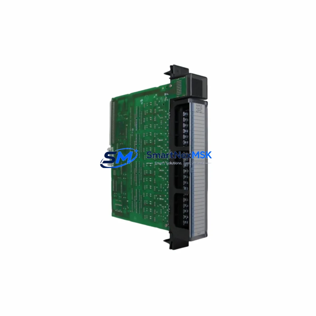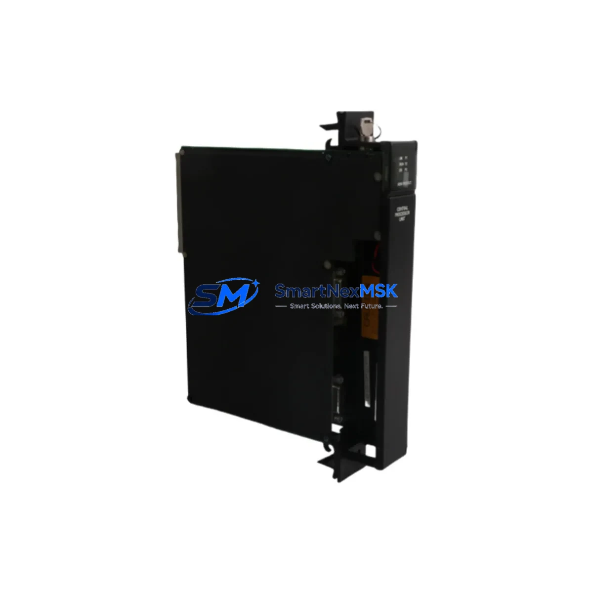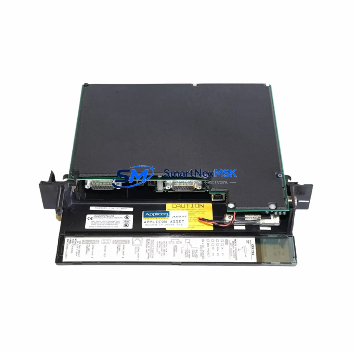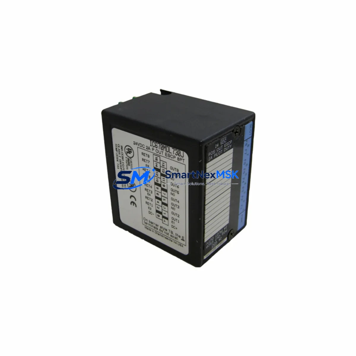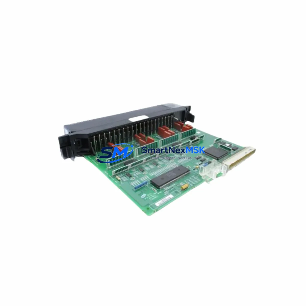
GE IC697MDL251 Maintenance-Ready Spare for Series 90-70 Automation
The GE IC697MDL251 is an original 32-point, 24VDC discrete input module designed for the GE Series 90-70 programmable logic controller platform. For maintenance engineers managing aging automation infrastructure, this module represents a critical spare that directly impacts system uptime. Whether you are executing a planned shutdown inspection, responding to an unplanned fault, or building a strategic spare parts inventory for a high-availability control cabinet, the IC697MDL251 is a field-proven component that supports rapid restoration of discrete I/O functionality without requiring rack reconfiguration or software re-mapping.
Sourced as an original GE Automation & Controls component, each unit undergoes pre-shipment functional testing to verify channel integrity, input threshold response, and backplane communication. With a 12-month warranty and documented compatibility with the Series 90-70 rack architecture, this module is suitable for both emergency replacement and long-term lifecycle extension of installed systems.
Spare Maintenance Table
| Parameter | Specification |
|---|---|
| Part Number / SKU | IC697MDL251 |
| Brand | GE Automation & Controls (GE Fanuc) |
| Series | Series 90-70 |
| Module Type | Discrete Input Module |
| Input Points | 32-point |
| Input Voltage | 24VDC |
| Input Logic | Positive / Sink |
| Backplane Compatibility | Series 90-70 Rack (IC697CHS750, IC697CHS782, IC697CHS790) |
| CPU Compatibility | IC697CPU731, IC697CPU771, IC697CPU781, IC697CPU782 |
| Installation | Hot-swap capable with rack power cycling recommended for first install |
| Operating Temperature | 0°C to 60°C |
| Relative Humidity | 5% to 95% non-condensing |
| Origin | United States |
| Condition | Original, pre-shipment tested |
| Warranty | 12 Months |
| Application | Discrete field signal acquisition, PLC I/O expansion, control cabinet integration |
| Maintenance Recommendation | Inspect field wiring terminals, verify 24VDC supply rail, confirm LED channel status on power-up |
Maintenance Planning for Continuous Operation
When replacing the IC697MDL251 in a Series 90-70 control cabinet, a disciplined maintenance engineer will treat the module swap as an opportunity to audit the surrounding electrical environment. Begin by verifying the 24VDC power supply feeding the input circuit — a degraded or undersized supply rail is a common root cause of intermittent input faults that are misdiagnosed as module failure. If the cabinet uses a dedicated DC power distribution module such as the IC697PWR711 or IC697PWR724, check output voltage under load and inspect the fuse or circuit breaker protecting the 24VDC bus.
Next, inspect the terminal block wiring connected to the IC697MDL251’s field-side connectors. Loose terminations, corroded contacts, or undersized conductors on high-cycle discrete inputs — such as proximity sensors, limit switches, or pushbutton circuits — can cause false input states that accelerate module wear. If the cabinet includes an IC697MDL240 or IC697MDL241 (16-point discrete input variants), cross-check those modules for similar symptoms, as they share the same backplane slot architecture and field wiring conventions.
For systems where the IC697MDL251 interfaces with relay output modules such as the IC697MDL940 or IC697MDL341, verify coil voltage continuity and contact integrity on the output side. A welded relay contact or a shorted output channel can back-feed voltage into the input circuit, causing diagnostic confusion during fault isolation. Inspect the IC697BEM711 or IC697BEM713 bus expansion modules if the rack is part of a multi-rack configuration, as backplane communication faults can manifest as false input reads on discrete modules.
If the system includes an IC697CMM711 or IC697CMM742 communications module for Ethernet or serial connectivity, confirm that the CPU scan cycle is not overloaded — excessive scan time can cause input latency that mimics hardware faults. For cabinets with signal isolation requirements, verify that any interposing signal isolators or barriers between field devices and the IC697MDL251 input terminals are within calibration and rated for the 24VDC input threshold. Finally, if an IC697MDL252 (the 32-point 120VAC variant) is installed in an adjacent slot, ensure there is no cross-wiring between AC and DC input circuits, which is a safety-critical inspection point during any I/O module replacement.
Site Replacement Workflow
Step 1 — Pre-replacement verification: Confirm the replacement IC697MDL251 matches the existing module’s firmware revision if the CPU requires a specific I/O compatibility level. Document the current channel LED status and any active fault codes in the CPU diagnostic log before powering down.
Step 2 — Safe isolation: De-energize the 24VDC field supply to the module’s input terminals. Do not rely solely on the CPU’s I/O disable command — physically isolate the field wiring at the terminal block or disconnect the field connector from the module face.
Step 3 — Module extraction and insertion: Release the module locking tab, slide the IC697MDL251 out of the rack slot, and insert the replacement unit. Ensure the backplane connector seats fully — partial engagement is a common cause of post-replacement communication faults.
Step 4 — Power-up and verification: Restore 24VDC field power and observe the module’s channel LEDs. All inputs in a de-energized state should show OFF; energized field devices should illuminate the corresponding channel LED. Use the CPU’s I/O forcing function to verify each channel group if a full field-device test is not practical during the maintenance window.
Step 5 — Documentation and spare replenishment: Log the replaced module’s serial number, installation date, and fault history. Immediately initiate a replenishment order to restore your spare parts inventory to the defined minimum stock level, ensuring the next unplanned failure can be resolved within the same shift.
Spare Parts Support FAQ
Q1: Is the IC697MDL251 still available as a new original part, or only as refurbished?
We supply original GE IC697MDL251 modules sourced through authorized industrial distribution channels. Each unit is individually tested prior to shipment. Condition and availability are confirmed at the time of order. Contact [email protected] for current stock status.
Q2: How do I verify compatibility between the IC697MDL251 and my existing Series 90-70 CPU?
The IC697MDL251 is compatible with all standard Series 90-70 CPU modules, including the IC697CPU731, IC697CPU771, IC697CPU781, and IC697CPU782, when installed in a standard Series 90-70 rack. Compatibility is determined by rack type and CPU firmware revision. Provide your CPU catalog number and firmware version when placing an order and our technical team will confirm compatibility before shipment.
Q3: What does the 12-month warranty cover, and what is the replacement process?
The 12-month warranty covers manufacturing defects and functional failures under normal operating conditions. If a module fails within the warranty period, contact [email protected] with your order number and a description of the fault. We will arrange a replacement shipment or issue a credit, subject to inspection of the returned unit.
Q4: Can I stock multiple IC697MDL251 units as part of a long-term lifecycle extension strategy for an aging Series 90-70 system?
Yes. For facilities operating Series 90-70 systems beyond the original design lifecycle, maintaining a minimum of two IC697MDL251 spares per installed rack is a widely adopted practice among maintenance engineers. We support bulk procurement with consistent lead times and can provide a long-term supply agreement for customers with multi-site or multi-rack installations. Contact us to discuss volume pricing and scheduled delivery options.
© 2026 SMARTNEXMSK. All rights reserved.
Original Source: https://smartnexmsk.com
Contact: [email protected] | +86 18259474341