HIMA F7130A Retrofit-Ready Power Supply for HIMatrix Control Systems
The HIMA F7130A is a redundant power supply module engineered for safety-critical automation environments operating under IEC 61508 SIL 3 requirements. As legacy HIMatrix installations approach end-of-life or require capacity upgrades, the F7130A serves as the primary retrofit solution — enabling plant engineers to restore full redundancy, extend system service life, and avoid costly full-system replacements. Whether you are replacing a failed unit, upgrading an aging control cabinet, or migrating from an earlier HIMatrix PSU variant, the F7130A delivers the electrical and mechanical compatibility needed for a smooth, low-downtime transition.
Sourced directly from verified supply channels, each F7130A unit offered by SMARTNEXMSK undergoes pre-shipment functional testing and is backed by a 12-month warranty covering manufacturing defects and operational failures under normal industrial conditions.
Upgrade Compatibility Table
| Parameter | Details |
|---|---|
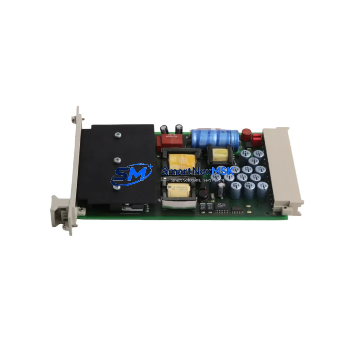
| Module SKU | F7130A |
| Manufacturer | HIMA Paul Hildebrandt GmbH (Germany) |
| Compatible Platform | HIMatrix Safety Controller Series |
| Safety Integrity Level | SIL 3 (IEC 61508) |
| Module Function | Redundant 24 VDC Power Supply for HIMatrix backplane |
| Backplane Interface | HIMatrix standard backplane connector (direct plug-in) |
| Installation Requirement | DIN rail or HIMatrix rack mount; no additional adapter required |
| Communication Compatibility | Compatible with SAFEETHERNET, ProfiSafe, and Modbus TCP configurations on HIMatrix |
| Replacement Recommendation | Direct replacement for F7130A and compatible with adjacent HIMatrix PSU slots |
| Commissioning Notes | Verify DC bus voltage, confirm redundancy switchover logic in SILworX, check module address assignment |
| Warranty | 12 Months — covers manufacturing defects and operational failure under normal use |
Retrofit Planning for Existing Automation Systems
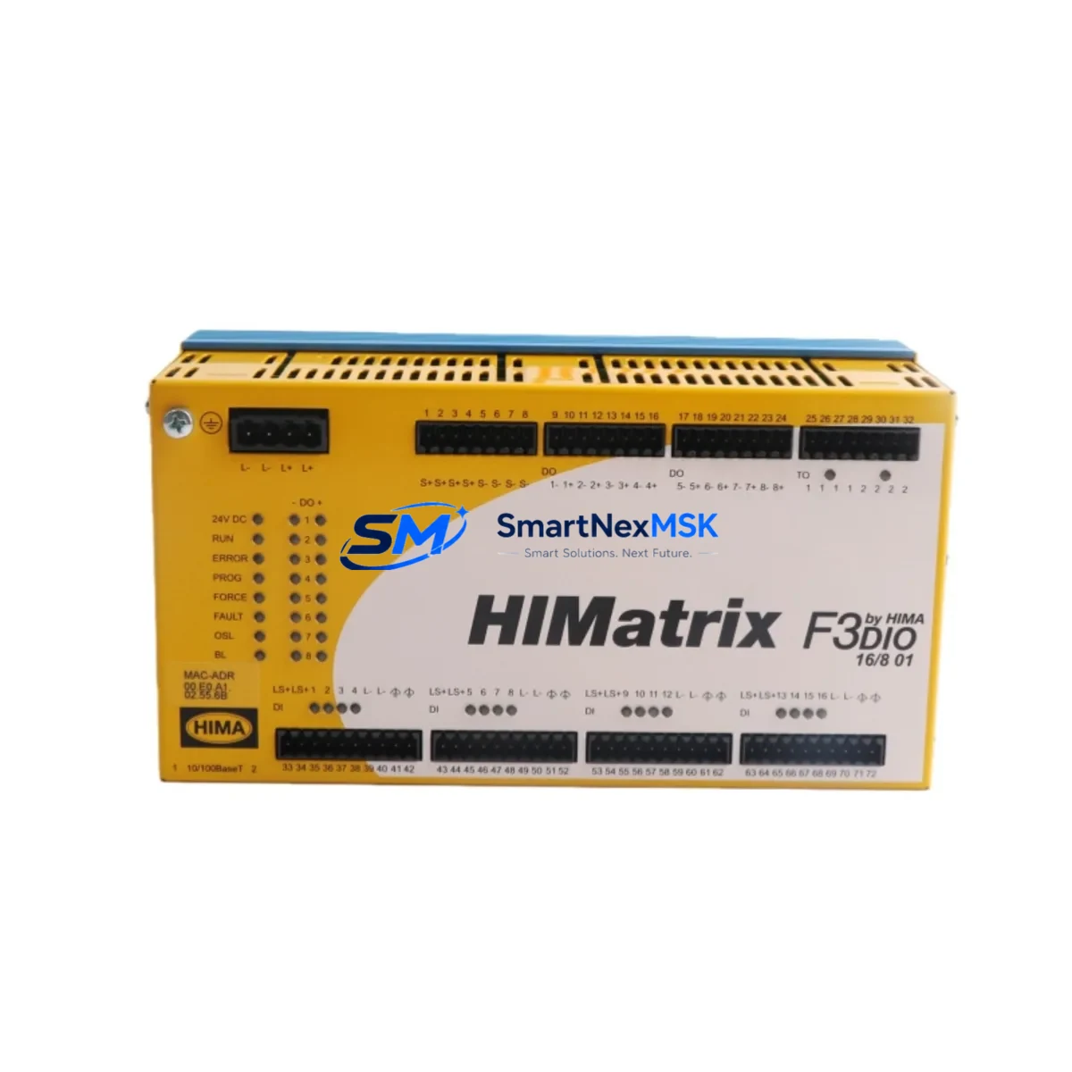
Retrofitting a HIMatrix-based safety system requires careful coordination across multiple hardware layers. The F7130A power supply module sits at the foundation of this process — without a stable, redundant power source, downstream modules including the F3 DIO 20/8 01 digital I/O module, the F3 AIO 8/4 01 analog input/output module, and the F3 CPU 0 central processing unit cannot maintain their SIL 3 operational status. Before swapping the PSU, engineers should document the current DC bus load across all installed modules and confirm that the F7130A’s output capacity covers the aggregate draw of the populated rack.
In systems where the HIMatrix rack also hosts communication modules such as the F3 COM 1 or F3 NET 1 for SAFEETHERNET or ProfiSafe links, the power budget calculation must include the communication module’s standby and active current draw. Failure to account for this is a common cause of intermittent faults after PSU replacement. Similarly, if the control cabinet integrates a HIMatrix HMI interface or a remote I/O expansion via F60 series remote modules, those loads must be factored into the pre-retrofit power audit.
Terminal wiring on the incoming 24 VDC supply side should be inspected and re-torqued to manufacturer specification during the retrofit window. Corroded or loose terminals are frequently discovered during PSU changeouts on systems that have been in continuous service for five or more years. If the existing wiring uses non-standard ferrule sizes, this is the appropriate time to standardize to the HIMatrix-recommended 1.5 mm² cross-section.
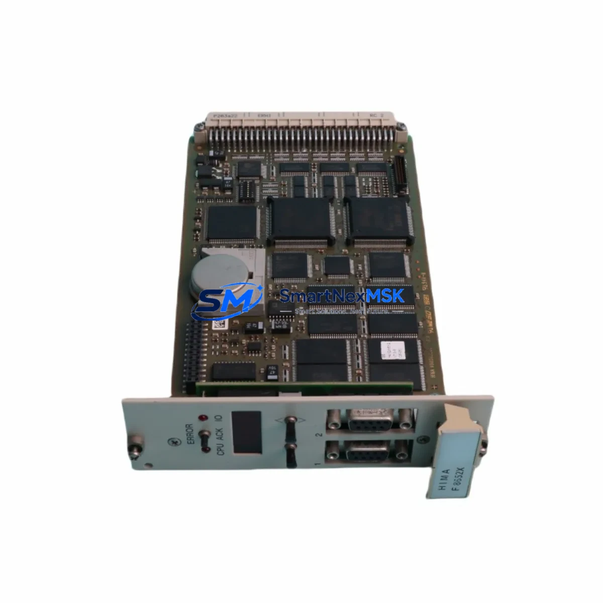
For systems using SILworX as the engineering tool, the module replacement does not require a full program download in most cases — the CPU retains the application logic in non-volatile memory. However, engineers should confirm the firmware version on the replacement F7130A is compatible with the installed SILworX project version before powering up. If the project was compiled under an older SILworX release, a compatibility check against the HIMA firmware release notes is recommended. The F3 CPU 0 will log a diagnostic event on first power-up with the new PSU, which should be acknowledged and cleared in the SILworX online monitor before returning the system to automatic mode.
Where the retrofit scope extends beyond the PSU to include I/O expansion — for example, adding an F3 DIO 20/8 01 to accommodate new field instruments — the module address configuration in SILworX must be updated prior to commissioning. Address conflicts between the new module and existing F3 AIO or communication modules will prevent the CPU from entering RUN state. A bench test of the new rack configuration using a SILworX simulation environment is strongly recommended before on-site installation.
Downtime Control During System Migration
Minimizing production downtime during a HIMatrix PSU retrofit begins with pre-staging. The replacement F7130A should be received, inspected, and bench-verified against the system’s power budget before the maintenance window opens. Having the module on-site and confirmed functional eliminates the most common source of extended downtime — discovering a shipping or compatibility issue only after the original module has been removed.
Where the HIMatrix configuration supports hot-standby redundancy, the PSU swap can often be performed with the system in a degraded-but-operational state, provided the redundant PSU slot is populated and healthy. Engineers should confirm the redundancy status in SILworX diagnostics before beginning the swap. If the system is running in simplex mode due to a prior PSU failure, a controlled process shutdown is required before the replacement, and the restart sequence should follow the HIMatrix commissioning checklist — power-up, CPU boot, I/O module initialization, communication link re-establishment, and HMI reconnection in that order.
Program logic integrity is preserved across the PSU swap because the F3 CPU 0 stores the application in non-volatile flash. There is no risk of program loss during a power cycle, but the engineer should verify that the CPU returns to RUN state automatically (if configured) or requires a manual RUN command via SILworX or the local keyswitch. Field instruments connected through the F3 DIO or F3 AIO modules will resume normal scanning once the CPU reaches RUN state, and the SAFEETHERNET or ProfiSafe communication links to partner controllers or F60 remote I/O stations will re-establish automatically within the configured watchdog timeout period.
Post-swap, a full I/O loop check is recommended for any terminals that were disturbed during the retrofit. Document the commissioning results, update the as-built drawings, and retain the pre-shipment test certificate for the F7130A as part of the system’s safety lifecycle documentation.
Retrofit Support FAQ
Q1: Is the F7130A a direct drop-in replacement for the existing HIMatrix PSU without program changes?
Yes. The F7130A is mechanically and electrically compatible with the HIMatrix backplane PSU slot. No program modification is required in SILworX for a like-for-like replacement. The CPU retains all application logic in non-volatile memory across the power cycle. A firmware compatibility check is recommended if the system is running an older SILworX project version.
Q2: What pre-commissioning checks are required before installing the F7130A?
Verify the incoming 24 VDC supply voltage is within the F7130A’s rated input range. Confirm the aggregate current draw of all installed modules — including F3 DIO, F3 AIO, F3 COM, and any remote I/O expansion modules — does not exceed the PSU’s rated output. Inspect and re-torque all terminal connections on the incoming supply wiring. Confirm the module firmware version is compatible with the installed SILworX release.
Q3: How is wiring compatibility handled when replacing an older HIMatrix PSU variant?
The F7130A uses the standard HIMatrix backplane connector for the DC bus and a screw-terminal block for the incoming 24 VDC supply. If the existing wiring was installed to HIMatrix specification, no rewiring is required. For systems where non-standard ferrule sizes or wire gauges were used, re-termination to the 1.5 mm² recommended cross-section is advised during the retrofit window.
Q4: What does the 12-month warranty cover, and what is the return process?
The 12-month warranty covers manufacturing defects and operational failures under normal industrial operating conditions. Units that fail within the warranty period are eligible for replacement or refund. To initiate a warranty claim, contact SMARTNEXMSK with the order reference, a description of the failure mode, and the pre-shipment test certificate supplied with the unit. Our technical team will coordinate the return and replacement logistics to minimize your system downtime.
© 2026 SMARTNEXMSK. All rights reserved.
Original Source: https://smartnexmsk.com
Contact: sales@smartnexmsk.com | +86 18259474341