
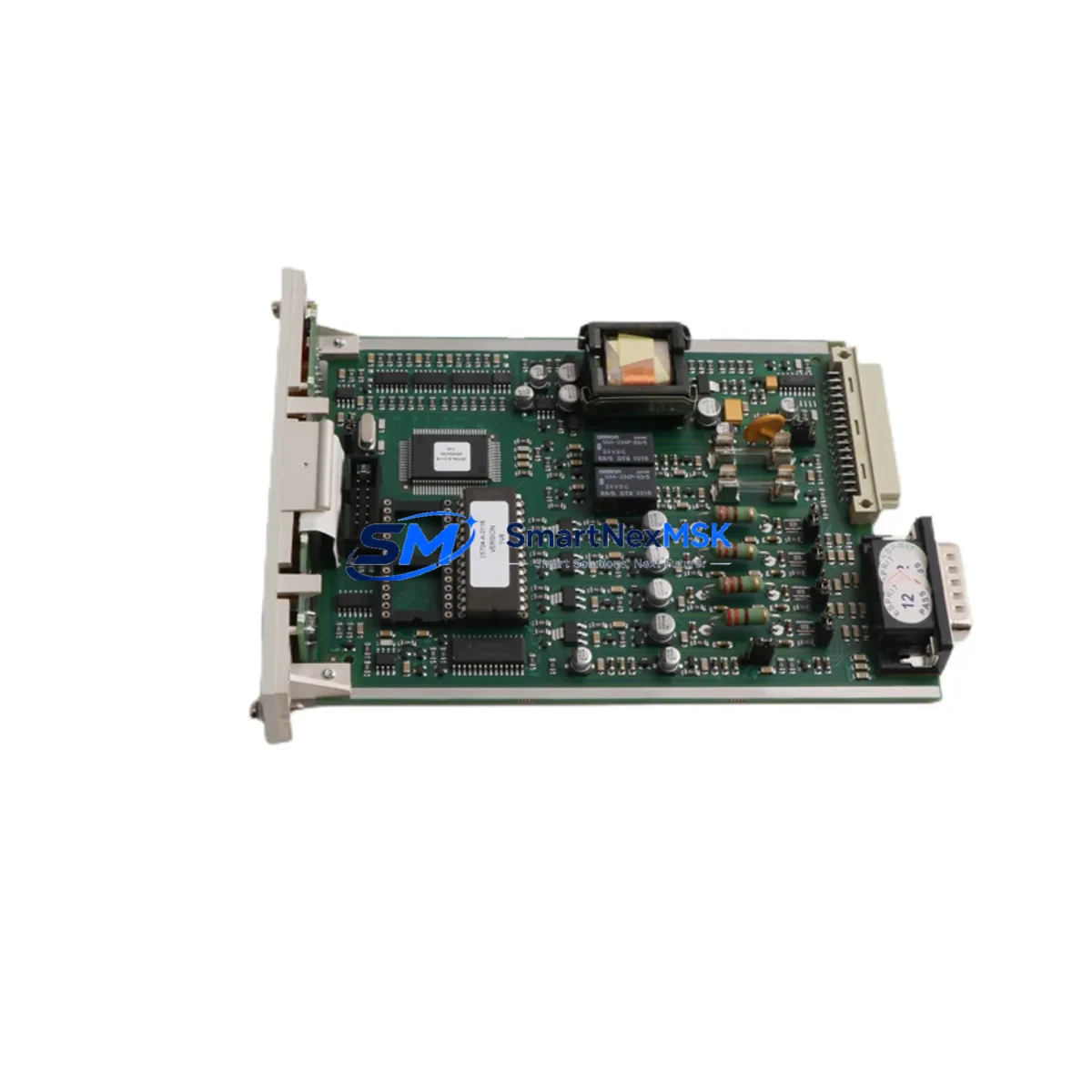
Honeywell 05704-A-0146 Maintenance-Ready Spare for 05704 Automation
The Honeywell 05704-A-0146 is an original fire control module designed for continuous-duty industrial safety and automation platforms. For maintenance engineers managing aging fire detection and suppression control systems, unplanned downtime caused by a failed control card can cascade into full-system shutdowns, regulatory non-compliance, and costly production interruptions. Stocking a verified, tested replacement unit of the 05704-A-0146 is the most reliable strategy to minimize mean time to repair (MTTR) and restore system integrity within a single maintenance window.
This module is sourced as an original Honeywell spare, inspected and functionally tested prior to shipment. Each unit ships with a 12-month warranty covering manufacturing defects and operational failures under normal industrial conditions. Whether you are executing a planned annual inspection, responding to a fault alarm, or decommissioning an end-of-life panel, the 05704-A-0146 provides a direct, compatible replacement that preserves your existing wiring topology and system configuration.
Spare Maintenance Table
| Parameter | Specification |
|---|---|
| Part Number / SKU | 05704-A-0146 |
| Brand | Honeywell |
| Series | 05704 Series Fire Control |
| Product Type | Fire Control Module |
| Origin | USA (Original Honeywell) |
| Compatibility | Honeywell 05704 Series fire and safety control panels; compatible with legacy and current-generation safety platforms using equivalent card-slot architecture |
| Installation | Direct card-slot replacement; no firmware re-flash required for like-for-like swap |
| Operating Environment | Industrial control cabinet; rated for standard industrial temperature and humidity ranges |
| Weight | 180 g (approx.) |
| Maintenance Recommendation | Inspect annually; replace immediately upon fault code or communication loss; keep one unit in on-site spare inventory |
| Pre-Shipment Testing | Functional test performed on every unit before dispatch |
| Warranty | 12 Months — covers manufacturing defects and operational failure under normal use |
Maintenance Planning for Continuous Operation
When replacing the 05704-A-0146 fire control module, a disciplined maintenance engineer will not stop at the card itself. The surrounding electrical environment must be verified to prevent repeat failures and to confirm the replacement unit enters service under clean conditions.
Begin with the 24 VDC power supply module feeding the control card rack — a degraded or noisy supply is a leading cause of premature card failure and intermittent fault alarms. Verify output voltage under load and check for ripple. Next, inspect the field wiring terminal blocks connected to the module’s I/O ports; loose or corroded terminals on the detection loop or suppression output circuits will generate false faults and can damage the new card’s input circuitry.
Check the loop isolation modules on any Class A or Class B detection circuits associated with this card. A failed isolator can mask a wiring fault and cause the replacement module to report the same error as the original. Similarly, inspect relay output modules used for suppression release or alarm notification — contact wear or coil degradation in these relays is often concurrent with control card faults in high-cycle environments.
For systems using RS-485 or proprietary communication buses to connect the fire panel to a building management system (BMS) or SCADA, verify the communication interface card and bus termination resistors are intact. A communication fault on the network side can be misdiagnosed as a control module failure. If the panel includes a network communication module for remote monitoring, confirm its firmware version is compatible with the replacement card.
Inspect the battery backup module and its associated charging circuit — fire safety systems must maintain operation during mains power loss, and a weak battery will cause the system to fail its self-test immediately after card replacement. Review the fuse and circuit protection assembly within the control cabinet; a blown fuse on the card’s supply rail is often the symptom of a downstream short that caused the original module failure, and replacing the card without clearing the fault will damage the new unit.
Finally, if the system includes a graphic annunciator panel or HMI display module, confirm that the replacement card’s address and zone configuration are correctly programmed to match the original before returning the system to service. Document all findings in the maintenance log and update the site’s spare parts inventory to reflect the consumed unit.
Site Replacement Workflow
Step 1 — Isolate and document. Place the fire panel in test mode per site safety procedures. Record the existing card’s address, zone assignments, and any custom configuration parameters before removal. Photograph the wiring connections.
Step 2 — Remove the failed module. Disconnect field wiring terminals in sequence, label each conductor, and extract the card from its slot. Inspect the slot connector for bent pins or contamination.
Step 3 — Install the 05704-A-0146 replacement. Seat the new card firmly, reconnect field wiring per the documented sequence, and verify terminal torque. The 05704-A-0146 is a direct form-fit-function replacement — no hardware modification is required for a like-for-like swap in compatible 05704 Series panels.
Step 4 — Configure and verify. Restore address and zone settings. Perform a full loop test on all detection circuits connected to the card. Confirm suppression output relay operation if applicable.
Step 5 — Return to service. Exit test mode, confirm system status is normal, and update the maintenance record. Replenish the on-site spare inventory with a new 05704-A-0146 unit to maintain readiness for the next event.
This workflow is designed to minimize total downtime to under two hours for a trained technician performing a planned replacement, and under four hours for an emergency unplanned swap.
Spare Parts Support FAQ
Q1: Is the 05704-A-0146 a direct replacement for the original Honeywell module, or does it require reconfiguration?
The 05704-A-0146 is an original Honeywell part and is a direct form-fit-function replacement for the same SKU in compatible 05704 Series panels. Address and zone parameters must be restored from your site documentation, but no hardware modification or firmware update is required for a like-for-like swap.
Q2: What does the 12-month warranty cover, and how is a warranty claim handled?
The 12-month warranty covers manufacturing defects and operational failures under normal industrial operating conditions. If a unit fails within the warranty period, contact our sales team with the order reference and a description of the fault. We will arrange a replacement or repair at no additional cost after technical review.
Q3: How should I manage spare inventory for the 05704-A-0146 in a multi-site operation?
For sites with a single fire panel using this module, we recommend maintaining one on-site spare at all times. For multi-panel or multi-site operations, a centralized regional spare pool of two to three units, combined with a documented replenishment trigger, provides the best balance of cost and availability. Our team can support blanket order arrangements for long-term supply continuity.
Q4: How is each unit tested before shipment, and what documentation is provided?
Every 05704-A-0146 unit undergoes functional testing prior to dispatch to verify electrical integrity and basic operational parameters. Units are shipped with a test confirmation and warranty certificate. If your site requires additional incoming inspection documentation, please advise at the time of order.
© 2026 SMARTNEXMSK. All rights reserved.
Original Source: https://smartnexmsk.com
Contact: [email protected] | +86 18259474341



