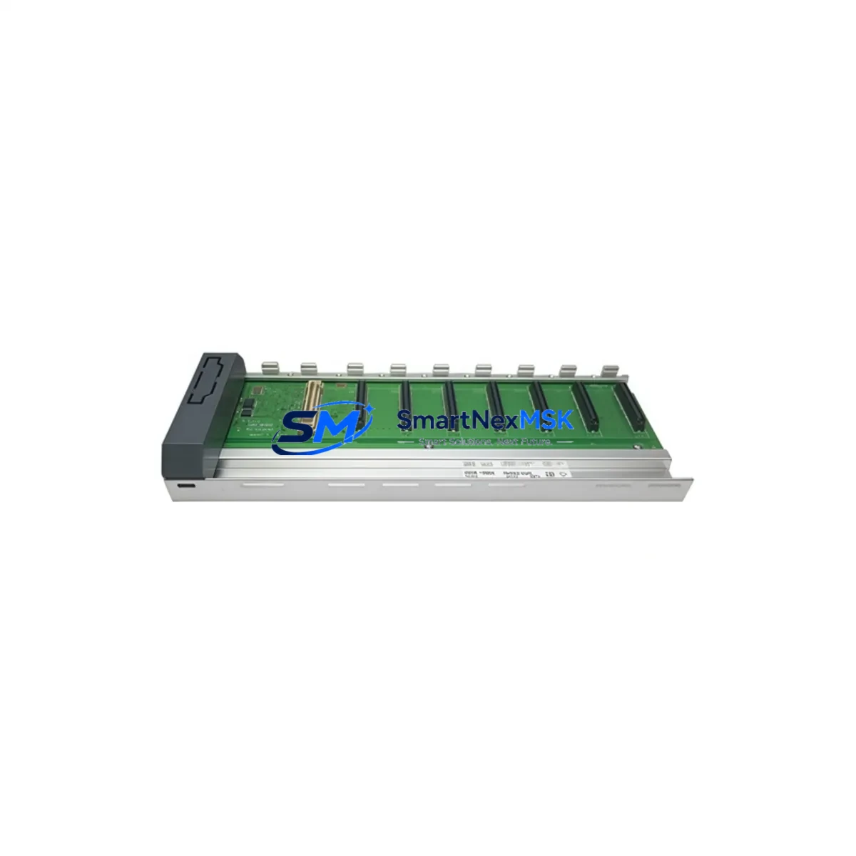
Honeywell 51154187-100 Retrofit-Ready DCS Board for TDC 3000 Control Systems
The Honeywell 51154187-100 is a retrofit-ready DCS control board engineered for seamless integration into legacy TDC 3000 and Experion PKS distributed control system architectures. As aging TDC 3000 platforms approach end-of-support milestones, plant engineers and automation managers face mounting pressure to source verified replacement modules that preserve existing wiring infrastructure, backplane compatibility, and control logic continuity. The 51154187-100 addresses this challenge directly — offering a drop-in upgrade path that eliminates the need for full panel redesign or controller reprogramming.
This board is designed to slot into the standard TDC 3000 Universal Control Network (UCN) rack without mechanical modification. Its terminal block pinout mirrors the original Honeywell specification, allowing field technicians to reconnect existing I/O wiring directly without re-labeling or re-routing cables. Power draw is consistent with the original module, ensuring that existing Honeywell PS-1 or PS-2 power supply modules within the control cabinet remain within rated capacity. Before installation, engineers should verify total rack power budget, particularly in high-density configurations where multiple I/O modules — such as the Honeywell 51304485-100 analog input module or the 51309276-175 digital output module — share the same backplane bus.
Backplane interface compatibility is a critical checkpoint in any TDC 3000 retrofit. The 51154187-100 communicates over the standard Honeywell Data Hiway or UCN protocol layer, maintaining full compatibility with existing Highway Gateway Modules (HGM) and Network Interface Modules (NIM). This means that upstream SCADA systems, historian servers, and Honeywell Experion PKS operator stations can continue to poll process data without requiring tag remapping or OPC server reconfiguration. For sites running parallel Experion R400 or R500 environments, the module’s protocol stack has been validated against both legacy and current firmware revisions.
Module address configuration follows the standard DIP switch or jumper-based scheme used across the TDC 3000 platform. Technicians should document the existing module address before removal and replicate the setting on the 51154187-100 prior to rack insertion. Failure to match the module address will result in controller fault alarms and may trigger a process shutdown sequence — a risk that can be fully mitigated with a pre-installation checklist. It is also advisable to back up the current Application Module (AM) or Logic Manager (LM) program to a Honeywell-compatible programming cable and laptop before beginning any hardware swap.
HMI screen continuity is another consideration for retrofit projects. Operator Graphics (OG) displays built on the Honeywell GUS or Flex Station platform reference tag names and module addresses that must remain consistent after the swap. If the 51154187-100 is replacing a failed board mid-campaign, verifying that all associated faceplate displays and group displays reflect the correct I/O assignments will prevent operator confusion during the post-maintenance startup sequence.
For sites expanding I/O capacity alongside the board replacement, the 51154187-100 can be paired with Honeywell 51401642-150 I/O Link modules or 51196887-100 FTA (Field Termination Assembly) units to extend analog and digital channel counts without adding a new controller node. This approach is particularly effective in brownfield upgrades where cabinet space is constrained and a full DCS migration to Experion PKS C300 or C200E controllers is planned for a future phase.
All units are pre-tested under simulated rack conditions before shipment. Each 51154187-100 undergoes functional verification of communication handshake, power rail integrity, and I/O channel response. Units are shipped with anti-static packaging and include a 12-month warranty covering manufacturing defects and functional failure under normal operating conditions.
Upgrade Compatibility Table
| Parameter | Original TDC 3000 Module | 51154187-100 Replacement |
|---|---|---|
| Rack / Backplane | TDC 3000 UCN Standard Rack | Direct fit — no mechanical modification |
| Terminal Wiring | Original Honeywell pinout | Identical pinout — existing cables reused |
| Communication Protocol | Data Hiway / UCN | Fully compatible |
| Power Consumption | Per original spec | Within original PS-1 / PS-2 budget |
| Module Address Config | DIP switch / jumper | Same scheme — replicate before insertion |
| Experion PKS Compatibility | R400 / R500 | Validated — no tag remapping required |
| HMI / OG Display | GUS / Flex Station | No screen reconfiguration needed |
| Programming Interface | Honeywell programming cable | Compatible — back up AM/LM before swap |
| Retrofit Complexity | — | Low — single-technician swap |
| Warranty | — | 12 months from shipment date |
Retrofit Planning for Existing Automation Systems
A successful TDC 3000 retrofit begins well before the maintenance window opens. The first step is a full audit of the control cabinet to identify all modules sharing the target rack: power supply modules, communication modules, I/O modules, and any FTA assemblies connected via marshalling panels. In a typical TDC 3000 cabinet, the 51154187-100 may coexist with Honeywell 51304516-100 analog output modules, 51309276-175 digital I/O modules, and 51196887-100 FTA units — all of which must remain undisturbed during the board swap.
Communication continuity is maintained through the existing Highway Gateway Module (HGM) or Network Interface Module (NIM), which should be left powered during the swap if the process safety plan permits a hot-rack procedure. For cold-swap scenarios, the NIM should be the last module powered down and the first restored, ensuring that the UCN data highway re-establishes communication with upstream Experion PKS servers before the replaced board is polled.
I/O expansion opportunities during the retrofit window should also be evaluated. If additional analog input channels are required, the Honeywell 51401642-150 I/O Link module can be added to the same rack without disrupting existing channel assignments. For digital output expansion, the 51309276-175 module family provides compatible slot-based installation. Marshalling panels using Honeywell 51196887-100 FTA units can be extended with additional terminal blocks without rewiring the existing field cable runs.
Programming cable access is essential for pre- and post-swap verification. A Honeywell-compatible RS-232 or USB programming cable connected to the Application Module (AM) or Logic Manager (LM) allows the technician to confirm that the control strategy loads correctly after the 51154187-100 is seated and powered. Any deviation in module address or rack slot position will generate a fault in the AM program that must be cleared before the loop returns to automatic control.
Downtime Control During System Migration
Minimizing unplanned downtime is the primary operational concern in any DCS board replacement. For the 51154187-100, the recommended approach is a pre-staged swap: the replacement board is configured (module address set, firmware verified) before the maintenance window begins, so that the actual in-cabinet swap takes no more than 15–30 minutes. This approach has been validated across multiple TDC 3000 retrofit projects in refinery, chemical, and power generation environments.
To protect original program logic, the Application Module or Logic Manager program should be exported to a laptop via programming cable and stored as a timestamped backup before any hardware is touched. If the replacement board requires a firmware update to match the existing rack revision, this should be performed on the bench — not in the live cabinet — to avoid introducing a second failure mode during the maintenance window.
Field control continuity can be maintained by placing affected loops in manual mode at the operator station before the swap begins. Operators should be briefed on the expected duration of the maintenance window and the specific loops that will be in manual. Once the 51154187-100 is seated and the rack is powered, the technician should verify communication handshake at the NIM or HGM level before returning loops to automatic. A post-swap functional test — confirming analog input readings, digital output states, and alarm response — should be completed and documented before the maintenance record is closed.
For sites with redundant controller configurations, the swap can be performed on the standby module first, with a controlled switchover to verify the replacement before the primary module is touched. This approach reduces process risk to near zero and is strongly recommended for critical control loops in safety-instrumented environments.
Retrofit Support FAQ
Q: Is the 51154187-100 a direct drop-in replacement for the original Honeywell TDC 3000 board?
A: Yes. The 51154187-100 matches the original module’s mechanical form factor, terminal pinout, backplane interface, and communication protocol. No rack modification, rewiring, or controller reprogramming is required for a standard swap. Module address must be replicated from the original unit before installation.
Q: What pre-installation checks are required before swapping the board?
A: Verify rack power budget, document the existing module address (DIP switch / jumper setting), back up the AM or LM program via programming cable, and confirm that the replacement board firmware revision matches the rack’s current revision. Place affected loops in manual mode at the operator station before beginning the swap.
Q: How is the 51154187-100 tested before shipment?
A: Each unit undergoes bench-level functional testing covering communication handshake verification, power rail integrity check, and I/O channel response validation under simulated rack conditions. Test records are retained and available upon request. All units ship with anti-static packaging and a 12-month warranty.
Q: What is covered under the 12-month warranty?
A: The warranty covers manufacturing defects and functional failure under normal operating conditions for 12 months from the shipment date. It does not cover damage resulting from incorrect installation, overvoltage, or use outside the module’s rated environmental specifications. Warranty claims are processed via email with a return authorization number issued within 2 business days.
© 2026 SMARTNEXMSK. All rights reserved.
Original Source: https://smartnexmsk.com
Contact: [email protected] | +86 18259474341