
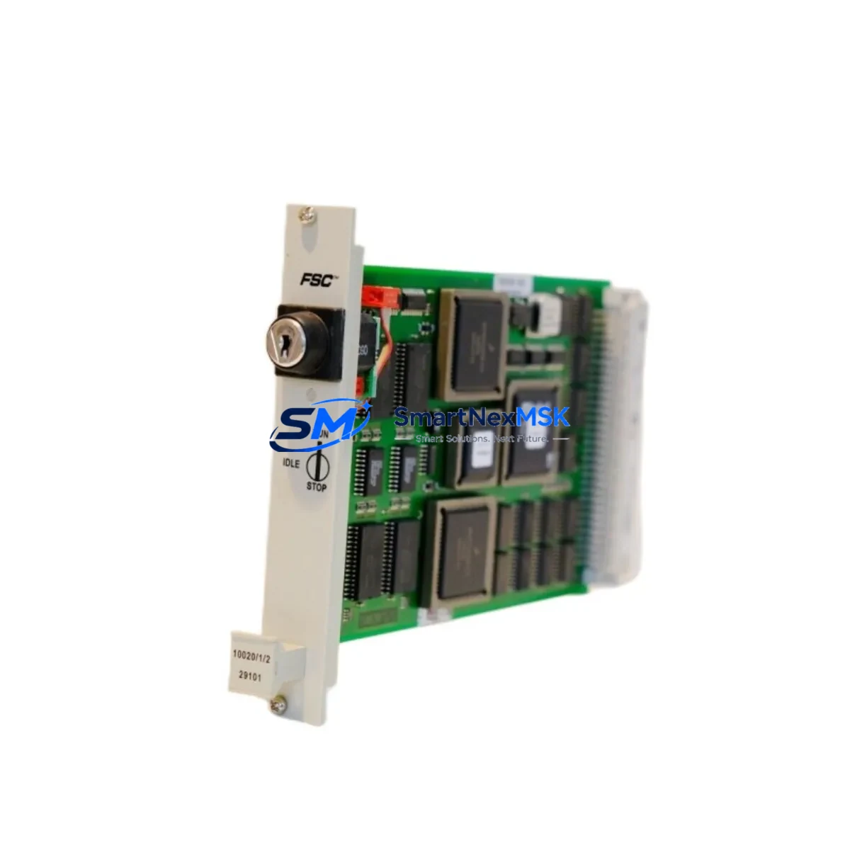
Honeywell 10020/1/2 Maintenance-Ready Spare for TDC 3000 Automation
The Honeywell 10020/1/2 is an original DCS CPU module engineered for the TotalPlant Solution (TPS) and TDC 3000 distributed control system platforms — two of the most widely deployed process automation architectures in refining, petrochemical, power generation, and continuous manufacturing environments. As a maintenance-ready spare, the 10020/1/2 is sourced, inspected, and dispatched to support rapid fault recovery, planned turnaround maintenance, and long-term system life extension for aging TDC 3000 control cabinets.
For maintenance engineers managing legacy Honeywell DCS infrastructure, securing a verified 10020/1/2 spare is a critical step in any preventive maintenance program. CPU module failures in TDC 3000 systems can cascade into full process shutdowns, making pre-positioned spares essential for minimizing mean time to repair (MTTR). This module is tested prior to shipment, covered by a 12-month warranty, and supported by long-term supply continuity from SMARTNEXMSK.
Spare Maintenance Table
| Parameter | Specification / Detail |
|---|---|
| Part Number / SKU | 10020/1/2 |
| Manufacturer | Honeywell |
| Compatible Platform | TDC 3000, TotalPlant Solution (TPS) |
| Module Type | DCS CPU / Processor Module |
| Form Factor | Card / Board Module (rack-mounted) |
| Country of Origin | United States |
| Operating Environment | Industrial control cabinet, climate-controlled panel room |
| Compatibility | TDC 3000 Universal Control Network (UCN), Local Control Network (LCN) |
| Installation | Hot-swap capable (system-dependent); follow Honeywell TDC 3000 maintenance procedures |
| Pre-shipment Testing | Functional verification performed before dispatch |
| Warranty | 12 Months from date of shipment |
| Condition | Original / Refurbished-to-spec (clearly stated at order confirmation) |
| Lead Time | In-stock: ships within 2–5 business days |
| Long-term Supply | Ongoing availability supported by SMARTNEXMSK spare parts network |
Maintenance Planning for Continuous Operation
When a TDC 3000 CPU module such as the 10020/1/2 is flagged for replacement during a control cabinet inspection or fault diagnostic, experienced maintenance engineers know that the CPU is rarely the only component under stress. A thorough site assessment and proactive spare parts strategy should encompass the full electrical and control architecture surrounding the module.
Begin with the power supply modules feeding the TDC 3000 rack — Honeywell’s dedicated rack power supplies (such as the 51109684-200 series) are common failure points in aging systems and should be inspected for output voltage drift, capacitor bulge, and thermal discoloration. Alongside the CPU, review the History Module (HM) and Application Module (AM) cards seated in the same LCN cabinet, as these share the same backplane and power bus.
I/O subsystems connected to the UCN should also be audited: High-Performance Process Manager (HPPM) I/O cards, analog input/output modules, and digital I/O modules are all candidates for proactive replacement during a planned outage. Pay particular attention to FTA (Field Termination Assembly) panels and their associated marshalling terminal blocks, which can develop intermittent contact faults that mimic CPU-level errors.
Communication integrity is equally critical. The LCN Interface Module and UCN Interface cards should be verified for clean signal transmission. If the system includes a Hiway Gateway (HG) or Application Module Gateway, these should be included in the inspection checklist. For sites running Honeywell’s PHD (Process Historian Database) or interfacing with third-party SCADA via OPC servers, communication module health directly impacts data continuity during and after a CPU swap.
Signal isolation is another area that maintenance teams often overlook until a replacement CPU reveals pre-existing noise issues. Signal isolators and conditioners on 4–20 mA loops feeding TDC 3000 analog inputs should be tested for drift. Surge protection devices on field wiring entry points and fuse terminal blocks within the marshalling cabinet should be inspected and replaced on a scheduled basis — not reactively.
Finally, for sites where the TDC 3000 interfaces with an Operator Station (OS) or legacy Universal Station (US), the HMI hardware — including GUS (Global User Station) workstations and their associated LCN node cards — should be assessed for hardware obsolescence. Maintaining a documented spare parts list that covers the CPU, power, I/O, communications, and HMI layers is the foundation of a resilient maintenance strategy for any TDC 3000 installation.
Site Replacement Workflow
Step 1 — Pre-replacement verification: Confirm the 10020/1/2 part number against the installed module’s label and the system’s hardware configuration report. Cross-reference with Honeywell TDC 3000 hardware documentation to validate slot assignment and firmware compatibility.
Step 2 — System state backup: Before removal, ensure the TDC 3000 system configuration and database are backed up to the History Module or an external archive. For redundant CPU configurations, verify the standby module is healthy and ready to assume control.
Step 3 — Safe module extraction: Follow Honeywell’s ESD (electrostatic discharge) handling procedures. Power down the affected card slot if hot-swap is not supported in your configuration. Document the physical slot position and any jumper or DIP switch settings on the outgoing module.
Step 4 — Install and initialize: Seat the replacement 10020/1/2 firmly into the backplane connector. Apply power and observe the module’s LED status indicators for normal boot sequence. Allow the TDC 3000 system to re-synchronize the new CPU with the active network.
Step 5 — Functional validation: Confirm all I/O points, control loops, and communication links are operating normally. Run a full alarm scan and verify historian data continuity. Document the replacement in the site maintenance log with date, technician, and module serial number.
This workflow supports minimal downtime, maintains system compatibility, and ensures the replacement is traceable for future audits and warranty claims.
Spare Parts Support FAQ
Q1: Is the Honeywell 10020/1/2 a direct drop-in replacement for the installed module?
The 10020/1/2 is designed as a direct replacement within compatible TDC 3000 and TotalPlant Solution rack configurations. Compatibility should be confirmed against your system’s hardware revision and firmware version prior to installation. SMARTNEXMSK can assist with compatibility verification before shipment.
Q2: What pre-shipment testing is performed on this module?
Each 10020/1/2 unit undergoes functional verification testing before dispatch. This includes power-on self-test validation and visual inspection for physical defects. A test report is available upon request. The module is covered by a 12-month warranty from the date of shipment.
Q3: How should this spare be stored if not immediately installed?
Store the 10020/1/2 in its original ESD-protective packaging in a dry, temperature-controlled environment (typically 0–40°C, <85% RH non-condensing). Avoid stacking heavy items on the module. Inspect the module annually if held in long-term storage and re-test before deployment.
Q4: What is the recommended inventory strategy for TDC 3000 CPU modules?
For critical process installations, maintaining a minimum of one cold-standby 10020/1/2 spare per control cabinet is recommended. Sites with multiple TDC 3000 cabinets or 24/7 continuous operations should consider a two-unit buffer. Coordinate with SMARTNEXMSK for volume pricing and long-term supply agreements to ensure availability as the TDC 3000 platform matures.
© 2026 SMARTNEXMSK. All rights reserved.
Original Source: https://smartnexmsk.com
Contact: [email protected] | +86 18259474341



