
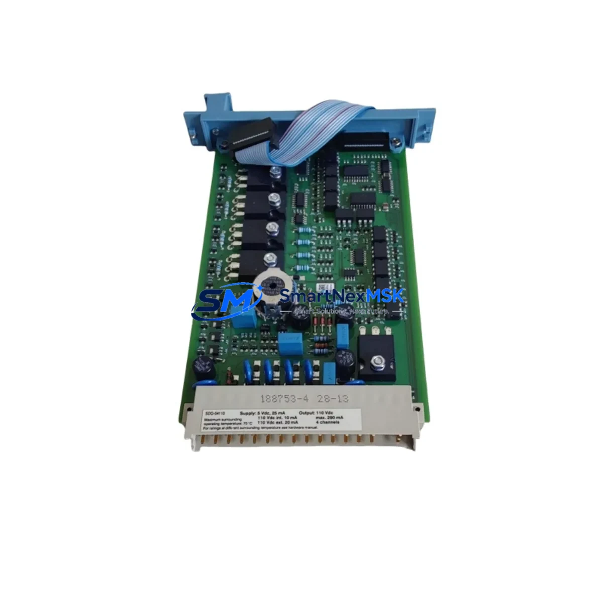
Honeywell 10102/2/1 Retrofit-Ready Diagnostic & Battery Module for TDC 3000 Control Systems
The Honeywell 10102/2/1 is a retrofit-ready diagnostic and battery backup module engineered for seamless integration into TDC 3000 distributed control system (DCS) architectures. As a direct functional replacement for the discontinued 10006/2/1 and 10106/2/1 modules, this unit is purpose-built to support aging control infrastructure upgrades, spare-parts replenishment, and system continuity programs across petrochemical, refining, power generation, and process manufacturing facilities.
Whether your facility is executing a phased modernization of a legacy TDC 3000 platform or responding to an unplanned module failure, the 10102/2/1 provides a verified drop-in solution that preserves existing backplane wiring, rack geometry, and firmware compatibility — minimizing engineering rework and reducing unplanned downtime exposure.
Upgrade Compatibility Table
| Parameter | Details |
|---|---|
| Primary SKU | 10102/2/1 |
| Compatible / Replaced SKUs | 10006/2/1, 10106/2/1 |
| Platform | Honeywell TDC 3000 DCS |
| Module Function | Diagnostic monitoring & battery backup |
| Backplane Interface | TDC 3000 standard card cage / rack slot |
| Installation Requirement | Direct slot replacement; no backplane modification required |
| Communication Compatibility | LCN (Local Control Network) compatible |
| Power Supply Requirement | Verify rack PSU capacity before hot-swap; confirm +5 VDC / +24 VDC rail loading |
| Retrofit Recommendation | Confirm firmware revision of host controller before installation; update if required |
| Commissioning Focus | Battery charge status, diagnostic LED verification, LCN node address confirmation |
| Warranty | 12 months from date of shipment |
Retrofit Planning for Existing Automation Systems
Successful integration of the 10102/2/1 into a live TDC 3000 environment requires systematic pre-installation planning. Engineers should begin by auditing the existing rack assembly — typically a TDC 3000 Universal Station (US) card cage or a High-Performance Process Manager (HPPM) rack — to confirm available slot positions, backplane bus integrity, and current power budget. The rack’s Power Supply Module (PSM) must be verified to support the additional load introduced by the replacement module, particularly if the existing PSM is already operating near rated capacity.
Terminal wiring associated with the legacy 10006/2/1 or 10106/2/1 should be documented and photographed prior to removal. Although the 10102/2/1 is designed as a functional replacement, terminal block pinouts should be cross-referenced against the site’s as-built drawings to confirm signal mapping. In installations where the original module interfaced with a Field Termination Assembly (FTA) or marshalling cabinet, the FTA wiring harness should be inspected for insulation condition and connector seating before the new module is energized.
For facilities running Honeywell LCN (Local Control Network) topology, the replacement module’s node address must be pre-configured to match the decommissioned unit’s LCN address. Failure to align node addressing will result in communication faults visible on the Universal Station (US) operator console and may trigger alarms on associated Application Module (AM) or History Module (HM) nodes. Where the TDC 3000 system interfaces with a Honeywell UCN (Universal Control Network) segment, the UCN gateway configuration should also be reviewed to ensure no address conflicts arise post-swap.
I/O continuity is a critical concern during any module replacement. If the 10102/2/1 is installed in a rack that also houses Analog Input (AI) or Analog Output (AO) modules sharing the same backplane segment, the I/O scan cycle should be monitored during commissioning to confirm no scan interruptions or data integrity errors. Where the facility uses a Data Hiway (DH) connection to link multiple TDC 3000 cabinets, the hiway traffic load should be assessed to ensure the replacement module does not introduce latency into the control loop.
HMI continuity is equally important. Operator displays built on the Honeywell Universal Station or migrated to a Honeywell Experion PKS supervisory layer should be reviewed to confirm that diagnostic status points associated with the replaced module are correctly mapped and that alarm setpoints remain active post-installation. Where facilities have partially migrated from TDC 3000 to Experion PKS, the TDC 3000 Gateway (C300 controller bridge) configuration should be validated to ensure the new module’s diagnostic outputs are correctly passed through to the Experion server.
Programming cable access may be required during commissioning if the module’s internal parameters need adjustment. A Honeywell CE (Control Engineer) workstation with the appropriate TDC 3000 software revision should be available on-site during the cutover window to support any required parameter downloads or configuration verification steps.
Downtime Control During System Migration
Minimizing production impact during a TDC 3000 module replacement requires a structured cutover methodology. The recommended approach is to schedule the physical swap during a planned maintenance window, with the process unit placed in a safe, stable operating state — ideally with critical control loops transferred to manual mode or backed up by a redundant controller path where available.
Before removing the legacy 10006/2/1 or 10106/2/1, a full backup of the TDC 3000 database should be performed from the Universal Station or the site’s engineering workstation. This backup preserves all control strategy logic, tuning parameters, alarm configurations, and historian tag assignments, ensuring that any unexpected post-swap anomaly can be recovered without data loss.
The 10102/2/1 should be bench-tested and powered up in an offline rack prior to field installation wherever possible. This pre-commissioning step confirms battery charge status, verifies diagnostic LED behavior, and validates that the module’s firmware revision is compatible with the host system before it enters the live control environment. Units supplied by SMARTNEXMSK are shipped after functional testing and include a test report confirming operational status.
During the live cutover, the module swap itself typically requires less than 15 minutes of physical work. The majority of the cutover window should be allocated to post-installation verification: confirming LCN node communication, checking diagnostic status on the operator console, verifying battery backup function, and monitoring the first 30 minutes of operation for any latent faults. A structured commissioning checklist — covering power-on sequence, communication link verification, I/O scan confirmation, and alarm acknowledgment — should be completed and signed off before the process unit is returned to automatic control.
Where a hot-swap is unavoidable due to operational constraints, the site’s safety instrumented system (SIS) and emergency shutdown (ESD) logic should be reviewed in advance to confirm that the module replacement will not inadvertently trigger a protective trip. Coordination with the control room operator is essential throughout the swap sequence.
Retrofit Support FAQ
Q1: Is the 10102/2/1 a direct drop-in replacement for the 10006/2/1 and 10106/2/1?
Yes. The 10102/2/1 is functionally compatible with both the 10006/2/1 and 10106/2/1 in standard TDC 3000 rack configurations. The backplane connector and slot form factor are identical. However, engineers should verify the firmware revision of the host system and confirm terminal wiring against site as-built drawings before installation, as minor hardware revisions across TDC 3000 generations may affect specific diagnostic feature sets.
Q2: What pre-installation checks are required for wiring and terminal compatibility?
Prior to installation, document all existing terminal connections on the legacy module and cross-reference against the 10102/2/1 wiring diagram. Confirm that the Field Termination Assembly (FTA) or marshalling panel connections are correctly mapped. Inspect terminal block condition and replace any corroded or damaged terminals before energizing the new module. Confirm power rail voltages at the rack PSU output before slot insertion.
Q3: How is the LCN node address configured on the replacement module?
The LCN node address is typically set via DIP switch or jumper configuration on the module PCB, depending on the hardware revision. The address must match the decommissioned module’s LCN node assignment exactly. After installation, the node should be confirmed as active on the LCN from the Universal Station system display. If the node does not appear within 2–3 minutes of power-on, check LCN cable connections and verify the address configuration against the system’s node assignment table.
Q4: What does the 12-month warranty cover, and how are units tested before shipment?
All 10102/2/1 units supplied by SMARTNEXMSK are functionally tested prior to shipment, covering power-on behavior, diagnostic output verification, battery charge circuit function, and communication interface integrity. The 12-month warranty covers manufacturing defects and functional failures under normal operating conditions from the date of shipment. Units are packaged in anti-static ESD-safe materials with individual test documentation included. For warranty claims or technical support, contact [email protected].
© 2026 SMARTNEXMSK. All rights reserved.
Original Source: https://smartnexmsk.com
Contact: [email protected] | +86 18259474341



