
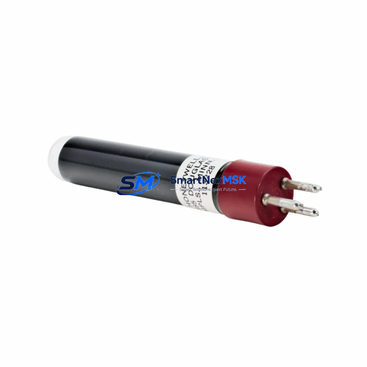
Honeywell 113228/U Maintenance-Ready Spare for RM7800 Automation
The Honeywell 113228/U is an original UV flame sensor engineered for continuous-duty burner management applications. Designed as a direct OEM-grade replacement for RM7800 series and R7847 burner control systems, this spare part is a critical component in combustion safety circuits across industrial boilers, process heaters, thermal oxidizers, and power generation equipment. For maintenance engineers managing planned shutdowns or responding to unplanned flame-failure alarms, having a verified 113228/U in the spare parts cabinet is the single most effective way to minimize combustion system downtime.
Each unit shipped by SMARTNEXMSK is sourced from authorized supply channels, individually inspected, and electrically tested prior to dispatch. The 113228/U is packaged to prevent electrostatic and mechanical damage during transit, and arrives with full traceability documentation. A 12-month warranty covers all units against manufacturing defects and functional failure under normal operating conditions.
Whether you are executing a scheduled annual inspection, responding to a nuisance trip, or building out a critical-spares inventory for a multi-burner installation, the 113228/U delivers the response speed and reliability that industrial combustion systems demand.
Spare Maintenance Table
| Part Number / SKU | 113228/U |
| Brand | Honeywell |
| Series Compatibility | RM7800, RM7800L, RM7800M, RM7840, R7847 |
| Product Type | UV Flame Sensor |
| Detection Principle | Ultraviolet (UV) flame detection |
| Supply Voltage | 120 VAC / 240 VAC (per system configuration) |
| Operating Temperature | -40°C to +70°C |
| Mounting / Interface | Direct plug-in to RM7800 series amplifier socket |
| Application Environment | Industrial boilers, process heaters, thermal oxidizers, power generation |
| Origin | United States |
| Condition | Original, new, tested before shipment |
| Warranty | 12 Months — covers manufacturing defects and functional failure |
| Maintenance Recommendation | Replace every 2–3 years or upon flame-failure alarm; inspect UV window for contamination at each scheduled shutdown |
Maintenance Planning for Continuous Operation
When a 113228/U UV flame sensor is flagged for replacement during a planned inspection or after a nuisance trip, experienced maintenance engineers know that the sensor itself is rarely the only component that warrants attention. A thorough combustion system inspection should extend to the full burner management circuit to prevent repeat failures and maximize the interval before the next shutdown.
Start with the RM7800L or RM7800M burner control module — the primary logic controller that interprets the UV signal from the 113228/U. If the sensor has degraded, the control module’s amplifier input circuit may have been exposed to out-of-range signals over time. Verify the amplifier card or replace the R7847A1082 or R7847C1029 amplifier if flame signal strength readings are inconsistent after sensor replacement.
Inspect the Q7800A or Q7800B wiring subbase that the RM7800 control mounts onto. Loose terminals, corroded contacts, or cracked insulation on the subbase can cause intermittent flame-failure faults that are misdiagnosed as sensor failures. While the control cabinet is open, check the 120 VAC or 240 VAC power supply circuit feeding the burner management panel — voltage sags or transients are a common root cause of UV sensor degradation.
For installations with multiple burner zones, review the S7800A1001 or S7800B1001 display module for logged fault codes before clearing alarms. These display modules retain a fault history that can reveal whether the flame failure was a one-time event or part of a recurring pattern. If the system uses a BC7000 or BC1000 series burner controller in parallel, verify that the interlock wiring between the two control loops is intact.
Check all terminal blocks and DIN-rail mounted fuse holders in the burner control cabinet. A blown fuse on the UV sensor supply circuit is a common secondary fault that can prevent a new 113228/U from operating correctly after installation. Inspect signal isolation relays between the burner management system and the plant DCS or PLC — degraded relay contacts can introduce noise into the flame signal circuit. Finally, verify the condition of the UV sight tube and viewing port on the burner assembly itself; a contaminated or misaligned sight tube will cause a new sensor to fail prematurely regardless of its condition.
Site Replacement Workflow
Step 1 — Isolate and de-energize. Follow your site’s lockout/tagout procedure for the burner management panel. Confirm that the RM7800 control is de-energized and that the burner is in a safe, purged state before opening the control cabinet.
Step 2 — Remove the existing sensor. Unplug the 113228/U (or its predecessor) from the amplifier socket on the RM7800 control module. Note the orientation and any labeling before removal. Inspect the socket contacts for corrosion or mechanical damage.
Step 3 — Install the replacement 113228/U. Align the new sensor with the amplifier socket and press firmly until fully seated. No tools are required for the plug-in connection. Verify that the UV window is clean and unobstructed.
Step 4 — Re-energize and commission. Restore power to the burner management panel. Initiate a controlled burner start sequence and monitor the flame signal strength reading on the S7800 display module or via the plant DCS. A healthy UV signal should register above the minimum threshold within the first ignition trial.
Step 5 — Document and update the maintenance record. Record the replacement date, the new sensor’s serial number, and the observed flame signal strength in the equipment maintenance log. Update the spare parts inventory to trigger reorder of a replacement 113228/U for the next scheduled maintenance cycle.
This workflow supports a direct like-for-like replacement that maintains full system compatibility with the RM7800 series platform, eliminates the need for rewiring or reconfiguration, and restores the burner management system to full operational status with minimal downtime.
Spare Parts Support FAQ
Q1: What is the recommended spare parts lifecycle strategy for the 113228/U in a multi-burner installation?
For facilities operating three or more RM7800-controlled burners, we recommend maintaining a minimum of two 113228/U sensors in on-site inventory at all times. UV flame sensors are wear items with a typical service life of 3–5 years under continuous-duty conditions. Proactive replacement during planned annual shutdowns — rather than waiting for a flame-failure alarm — is the most cost-effective strategy for avoiding unplanned combustion system downtime.
Q2: How is the 113228/U tested before shipment?
Every 113228/U dispatched by SMARTNEXMSK undergoes electrical continuity and functional verification testing prior to packaging. Units that do not meet OEM performance specifications are quarantined and not shipped. Test records are retained and can be provided upon request for quality-critical applications.
Q3: Is the 113228/U compatible with both 120 VAC and 240 VAC RM7800 system configurations?
The 113228/U UV flame sensor is a passive plug-in component that interfaces with the amplifier circuit of the RM7800 control module. Compatibility with 120 VAC or 240 VAC system configurations is determined by the RM7800 control module and power supply, not by the sensor itself. Confirm your RM7800 model number and system voltage before ordering if you are unsure of your configuration.
Q4: What does the 12-month warranty cover, and how is a warranty claim processed?
The 12-month warranty covers manufacturing defects and functional failure under normal operating conditions from the date of shipment. It does not cover damage resulting from incorrect installation, exposure to conditions outside the specified operating range, or physical mishandling. To initiate a warranty claim, contact SMARTNEXMSK with your order reference, a description of the fault, and photographic evidence of the installation. Replacement units are dispatched upon claim verification.
© 2026 SMARTNEXMSK. All rights reserved.
Original Source: https://smartnexmsk.com
Contact: [email protected] | +86 18259474341



