
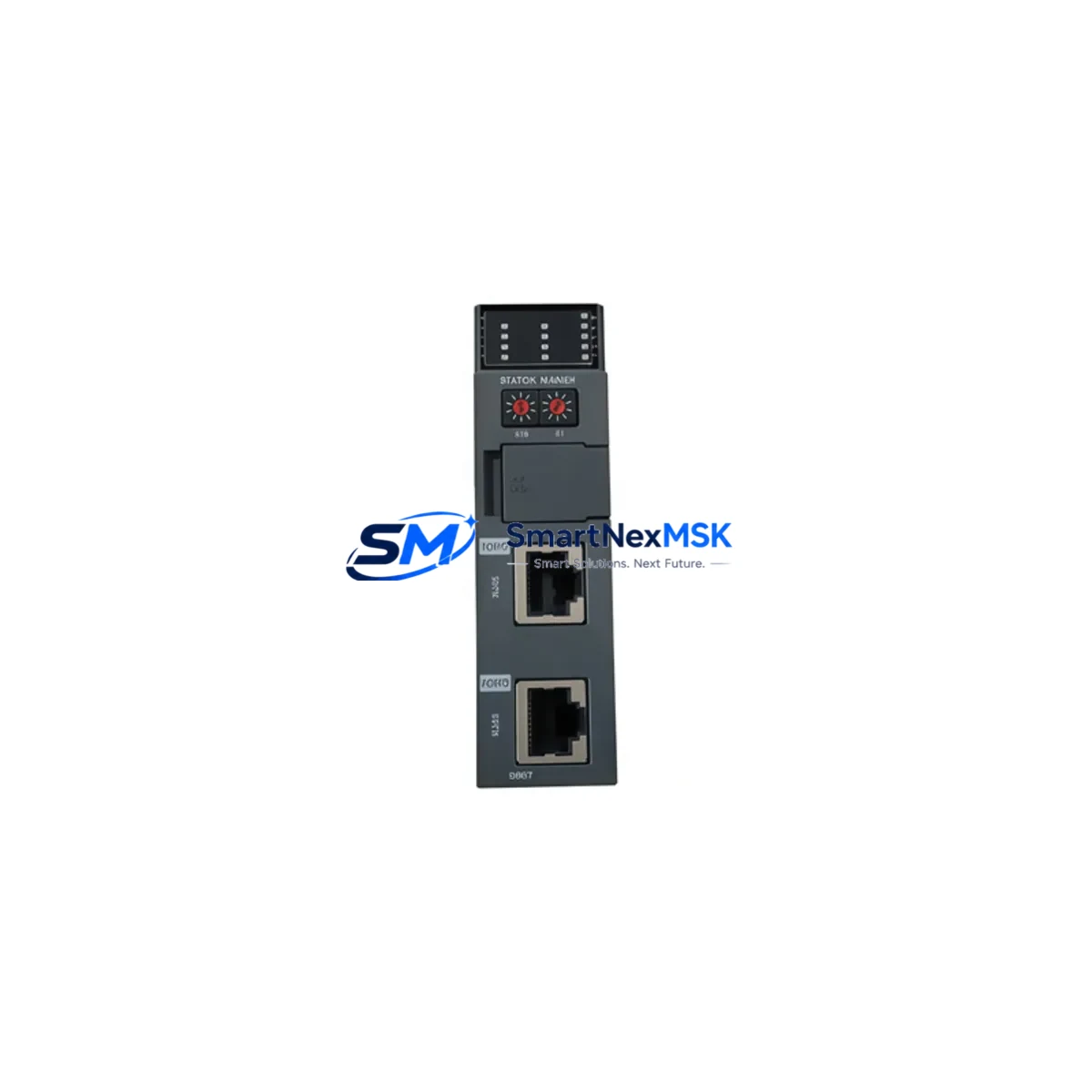
Honeywell 2MLR-DBDT Retrofit-Ready Redundant Expansion Driver for FSC Control Systems
The Honeywell 2MLR-DBDT is a redundant expansion driver module designed for the Honeywell FSC (Fail-Safe Controller) Series safety PLC platform. As legacy FSC systems approach end-of-life and spare parts become increasingly scarce, the 2MLR-DBDT has become one of the most sought-after retrofit and replacement components for engineers managing aging safety instrumented systems (SIS) in process industries including oil & gas, petrochemical, power generation, and chemical manufacturing.
This module serves as a direct retrofit replacement for discontinued or degraded redundant driver assemblies within the FSC backplane architecture. It supports seamless integration into existing FSC cabinets without requiring hardware redesign, making it the preferred choice for maintenance teams focused on minimizing downtime and preserving validated safety logic.
Upgrade Compatibility Table
| Parameter | Details |
|---|---|
| Compatible Platform | Honeywell FSC Series Safety PLC |
| Module Function | Redundant Expansion Driver |
| Backplane Interface | FSC standard backplane slot (direct plug-in) |
| Installation Type | DIN rail / panel-mount, compatible with existing FSC rack |
| Communication Compatibility | FSC internal bus; compatible with FSC communication modules |
| Wiring Compatibility | Terminal block wiring matches original 2MLR-DBDT pinout |
| Replacement Scope | Drop-in replacement for failed or end-of-life 2MLR-DBDT units |
| Commissioning Requirement | Address configuration via FSC programming tool; verify I/O mapping |
| Firmware / Program Compatibility | Compatible with existing FSC application logic; no recompilation required in most cases |
| Outgoing Test | Function-tested prior to shipment |
| Warranty | 12-Month Warranty from date of shipment |
Retrofit Planning for Existing Automation Systems
Replacing the 2MLR-DBDT in an operational FSC system requires careful pre-planning to ensure continuity of the safety function and avoid unplanned shutdowns. Before initiating the swap, engineers should audit the existing FSC rack configuration, confirming the slot address of the failed module and verifying that the replacement unit carries the same hardware revision where possible.
Power supply capacity is a critical first checkpoint. The FSC system’s power supply module — typically a dedicated 24 VDC redundant supply — must be verified to support the full load of the replacement 2MLR-DBDT alongside all co-installed modules. If the existing FSC power supply module is already operating near capacity, a parallel power audit of the entire control cabinet is recommended before proceeding.
Terminal wiring should be documented with photographs and wiring diagrams before disconnection. The 2MLR-DBDT interfaces with field I/O through the FSC terminal assembly; any deviation in terminal torque or wire routing can introduce signal integrity issues post-commissioning. Cross-reference the original wiring schedule against the FSC I/O module assignments to confirm channel-to-tag mapping remains intact.
Backplane seating is equally important. The FSC backplane connector must be inspected for bent pins or oxidation before inserting the replacement module. In systems where the FSC rack has been in service for over ten years, it is advisable to clean the backplane contacts and verify mechanical locking before powering up.
Module address configuration is handled through the FSC programming environment. After physical installation, the module address must be confirmed to match the original slot assignment. Any mismatch will cause the FSC controller to flag a configuration fault, preventing the safety system from entering run mode. This step is particularly important in multi-rack FSC architectures where the FSC expansion rack communicates with the primary controller via the FSC communication link module.
Program compatibility should be verified by reviewing the FSC application program’s I/O declarations. In most retrofit scenarios, the existing FSC application logic — including cause-and-effect matrices, voting logic, and trip functions — does not require modification when replacing a like-for-like 2MLR-DBDT. However, if the replacement unit carries a different firmware revision, a compatibility check against the FSC system release notes is recommended.
HMI screen updates may be required if the original SCADA or DCS interface references specific module health diagnostics. Operators using a Honeywell Experion PKS or third-party HMI connected to the FSC via Modbus or HART should verify that all diagnostic tags continue to resolve correctly after the module swap.
Communication link integrity should be confirmed end-to-end. The FSC communication module responsible for linking the safety controller to the DCS or BPCS must be tested for uninterrupted data exchange after the 2MLR-DBDT replacement. In systems using FSC serial communication modules or FSC Ethernet gateway modules, a full communication loop test is recommended before returning the system to operational status.
Field commissioning should follow the site’s management of change (MOC) procedure. A functional test of all I/O channels associated with the replaced module — including analog input modules, digital output modules, and any connected solenoid valve or shutdown valve — must be completed and documented before the safety system is returned to service.
Downtime Control During System Migration
Minimizing downtime during a 2MLR-DBDT replacement is achievable with disciplined pre-staging and a structured hot-swap or cold-swap protocol depending on the FSC system’s redundancy configuration. In fully redundant FSC architectures, the failed module can often be replaced while the redundant channel maintains the safety function, provided the system’s redundancy management logic is confirmed to be active and healthy prior to the swap.
Pre-staging the replacement 2MLR-DBDT — including bench verification of the module’s power-on self-test and output driver function — reduces on-site commissioning time significantly. Having the FSC programming tool connected and the application program loaded on a laptop at the control cabinet before the physical swap begins allows engineers to immediately verify module recognition and address assignment without delay.
Original program logic should be backed up to a secure location before any hardware change. The FSC application program, including all function block configurations, safety function assignments, and I/O channel parameters, should be exported and stored. This protects against accidental overwrite during the commissioning process and provides a verified restore point if unexpected issues arise.
Field control continuity can be maintained by placing the affected safety loops in manual bypass — following the site’s bypass management procedure — for the duration of the module swap. This approach keeps the process running while the safety function is temporarily managed by the operations team, and it eliminates the need for a full process shutdown in many retrofit scenarios.
Post-installation, a structured loop test covering all I/O channels associated with the 2MLR-DBDT should be completed within the planned maintenance window. Documenting the as-found and as-left condition of each channel supports regulatory compliance and provides a clear record for the next scheduled proof test of the safety instrumented function.
Retrofit Support FAQ
Q1: Is the Honeywell 2MLR-DBDT a direct drop-in replacement for the original module?
A: Yes. The 2MLR-DBDT is designed as a direct replacement for the original Honeywell FSC Series redundant expansion driver. The backplane connector, terminal wiring pinout, and module address configuration are compatible with the existing FSC rack without hardware modification. Minor firmware revision differences may require a compatibility check using the FSC system release documentation.
Q2: What commissioning steps are required after installing the replacement 2MLR-DBDT?
A: After physical installation, connect the FSC programming tool and verify that the module is recognized at the correct slot address. Confirm that all I/O channel assignments match the original configuration. Perform a functional test of all associated field devices — including any connected digital output modules, analog input modules, or shutdown actuators — before returning the safety system to run mode. Document all as-left values per your site’s MOC procedure.
Q3: How do I verify wiring compatibility before replacing the 2MLR-DBDT?
A: Cross-reference the existing wiring schedule against the 2MLR-DBDT terminal block pinout diagram. Photograph all existing wiring before disconnection. Verify terminal torque specifications and confirm that cable shielding and grounding arrangements match the original installation. Any deviation in wiring should be corrected before powering up the replacement module.
Q4: What warranty coverage is provided with the 2MLR-DBDT?
A: All 2MLR-DBDT units supplied by SMARTNEXMSK carry a 12-month warranty from the date of shipment. Each unit is function-tested prior to dispatch to verify power-on self-test completion and output driver operation. In the event of a warranty claim, our technical team will provide replacement or repair support with priority handling to minimize impact on your production schedule.
© 2026 SMARTNEXMSK. All rights reserved.
Original Source: https://smartnexmsk.com
Contact: [email protected] | +86 18259474341



